As a pre-order user for the Pixel 7 Pro; I wanted a screen protector and case. On preorder timeline; there were not a lot of options for screen protectors. Usually I go for GLASS protectors; not the silly “plastic” sheets. I thought the ZAGG InvisibleShield® Fusion Curve for Pixel 7 Pro was a glass product. The description on Googles site wasn’t very descriptive; but now that I look at it; it does say “glass-like”.
This product is way over priced at $50. It has a stupid applicator frame with piss poor instructions. It only comes with a single “protector” where others on Amazon have 3 or more for a much cheaper price. Don’t fall for the warranty verbiage either as it really doesn’t matter. You can read all about the horrible customer service on Amazon. Even Amazon had to lock down the review section because “Amazon has noticed unusual reviewing activity on this product. Due to this activity, we have limited this product to verified purchase reviews.“
Simply put; keep your money in your pocket; find something better for a more reputable company. Skip this Chinese company. Google should be ashamed for putting this product on their webpage.
Back in October 2018; I purchased a new 2018 F-150 Raptor from new dealer stock to replace my 2000 Dodge Dakota which I purchased new from a dealer in Oregon. Given the way Chrysler failed to support their products under warranty; I informed them that I would never own another Chrysler product again. If you want more details as to why I won’t support that company any more; I posted briefly about it here.
I bought the Raptor to replace my daily driver and to haul the occasional Pinball machine to/from events. One of it’s jobs is to haul my enclosed trailer when I’m taking more than one machine. The result is I needed a new drop hitch. I originally started with a 8inch drop; but that was really too low for other trailers – while it fit my trailer fine. I ran into this when a friend rented a Uhaul trailer and it was nearly dragging the ground. As a result I decided I needed an adjustable trailer hitch which then became obvious that I needed a way to store this trailer hitch when it isn’t in use. On my other truck; I basically left the hitch always on the truck and managed to hit it with my shins or sometimes the driveway on the way out of the house. I wanted to avoid that this time around. Originally; I thought I might fit the hitch in the center console; but it turned out to be too heavy and bulky. So I’ll also be talking about my storage solutions in this post.
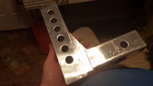
My saga began when I came across a Uriah Products UT623410 Adjustable Aluminum Mount with 3 Interchangeable Balls-6″ Drop on a Amazon Warehouse deal for a good price. In the past I had really good experience with AMW deals; where the packaging or minor issues which didn’t effect functionality were worth the discounted amount. The biggest problem with this mount was it was what I’d call heavily used. It appears the previous purchaser used it for a cross country trip; then boxed it back up and shipped it back to Amazon. Because of this I decided I wanted to clean it up and make it match the “Electric Blue” of my Raptor. I started with the drop mechanism. The two main pieces are made from a thick Aluminum alloy; so they tend to scratch and dent under heavy use. Specifically; the drop mech tends to “crease” on the lower part of the receiver when it’s rocking back and forth while hauling the trailer. I cleaned up the previous user’s creases with a file and some sandpaper: I proceeded to clean the part and then powder coat it with the blue powdercoat I had from a previous project.
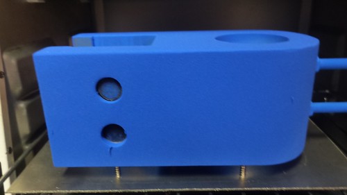
I did the same thing with the slidable ball mount; here’s the part getting the powdercoat: I used some carriage bolts sourced from Lowes to secure this heavy part on my makeshift powder coating rack.
Next, I used a scrap sheet of aluminum to make a makeshift “cooking” stand for use in the toasting oven. Here’s the part before heating: Here’s the part after curing the powder coat:
I did some more offline work to add a powder coated “raptor” to the ball mount on both sides. Sadly I didn’t take any pictures of this process. The process was that I basically put some Polyamide tape over the mount and then laser etched the raptor image into the powdercoat and tape. Once I had clean metal from the laser etch; I powdercoat a matte black onto the polyamide tape and re-baked the piece. Here’s the installed ball mount with the Raptor embellishment:
With the ball mount complete; I turned my focus on how to store the hitch when it’s not in use. This turned out to be tricky because I had already used up all the under rear seat storage with other items; so I needed a organized way to keep it out of the way while being able to quickly install it when needed. After some research; I decided I needed to use a Pelican Vault V200 Medium Case to store the hitch and all it’s accessories in “layers” inside the Pelican. I wasn’t keen on hand carving foam… and the foam that came with the Pelican wasn’t strong enough to resist the weight of the hitch. A plan solidified which involved laser cutting some high density PE foam on my cutter. Why PE? Because it’s laser safe ad can be bought readily on Amazon. Before I got to that point; I proceeded to work out the geometry in CAD before committing to lasering the foam and to make sure everything would fit.
I started by using a set of digital calipers to measure the various parts I wanted to put in the case and transferring the basic outline into a DXF file. Most of the parts are under 2inches tall. with the notable exception of the ball mount. This is why I decided on the 2inch thick foam and then stack two layers of the foam to hold the various other miscellaneous pieces. For the Ball mount; I’d have to mount it vertically to keep the horizontal space for the “L” shape of the drop. A couple of design itterations later; here’s the final bottom layer as seen in CAD: The bottom bascially holds the three balls, the ball mount, the drop, one of the locks, and one of the ball pegs. The Top Layer housed the remaining parts: This layer houses the remaining parts:
remaining Z-height of the Ball mount,
The remaining Z-height of the 2-3/4 ball,
The remaining ball peg,
a second hitch lock,
The unused receiver hitch peg,
a tonge lock,
a spot for the Plano Case – which holds the misc clips,
and a spot for the Keysmart keyring (for the various keys)
I wanted the bottom of the locks and pegs to be flush with the top of the given layer so I made some “filler” parts out of 1inch. I wanted the ball mount to be “snug” between the first and second layers; so I also made a filler out of 1/2inch foam to mount on top of the second layer.
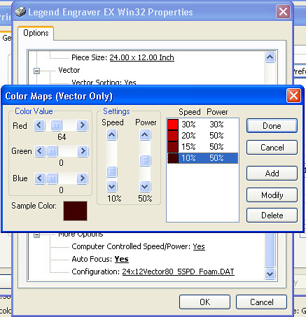
With the CAD work done; I started trying to laser cut this PE foam. Turned out to be quite tricky for several reasons. First; there’s no published power/speed values for the foam. Second; my poor Epilog 24TT laser just lacks the power to punch thru the foam. My laser specs for a new tube is 25watts – but I’m sure mine has aged and probably puts out 20ish watts if that. Third; the 2inch foam is really too thick for the 2in lense my machine has. Focusing on top of the 2in foam; the laser’s focal distance causes almost unmanageable beam spread at about 1/2inch from the bottom of the 2in foam. This causes extreme melting at the “bottom” of the layer. Again because the focal length of a 2in lens; it was impossible to re-focus the laser to cut the final inch in z-depth on the foam. Regardless; I was able to cut the pieces – which really turned out better than if I’d tried to hand cut them. I don’t remember specifically what I used for power; but it was multiple (read 4-6) passes with varying power. I started with 30% power at 30% speed for the initial cut. This was dialed in by doing some test cuts to maximize cutting and minimizing shrinkage due to excessive heat at the cut line. With each pass; I reduced the speed by 10, 5, and 5 while adding 20% more power. Again; this was to “punch” thru the remaining material without being able to refocus the 2in focal length. Here’s the final “table” of the power settings used for each pass:
The 1 inch and 0.5 inch foam cut much easier; I think the 1inch foam cut in 2 passes and the 0.5inch with one pass at 30/30. With the foam cut; it had to put the parts together. The only way to really get this foam to glue to itself is using CyanoAcrylate glue. I forget where I read this; but Google search basically indicated this is how the “industry” makes custom shipping foam out of this stuff. I did this by putting the CyanoAcrylate Accelerator in the Needle tip Glue Bottle. Then I put the Accelerator on one side of a seem and the CA glue on the other. Then using my fingers; pressing the seem together for about 15-20seconds. Take my advice here… unless you want to be dealing with superglued spots on your finger tips; use some disposable latex gloves. The CA glue still gets everywhere… so make sure you’re wearing “junk” clothes. Even after 20seconds; the glue really hasn’t set well. So once you completely finish a “layer”; leave it to set overnight so the CA glue will completely “cure”. The Accelerator is suppose to make this bonding instant… but either I was using too much of it… or the glue had a longer shelf life. So since I was going to be using this foam for really heavy things; I just left it to cure overnight.
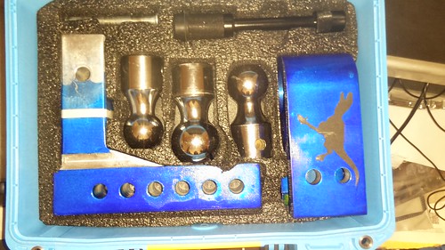
What did all of this work yield? Here’s the bottom layer populated with it’s various pieces:
Here’s the top layer with it’s pieces. This was a earlier non-reworked version which didn’t have the tounge lock or keysmart keyring areas in the empty spaces.
The Plano Pocket Box holds the various clips, o-rings, and extra keys for the locks:
IIRC, I reused the compressible foam sent with the vault case for the top of the lid so that the layers would remain snughly compressed in the Vault case:
I used the Premium Cinch Strap to secure the case in the bed of my truck by securing it to the Camper shell’s linear actuator:
With that project is complete. I’ve used the case about 3-4 times and it makes the whole storing of the drop hitch easy.
For years I’ve been limping along with a very noise older model Air compressor for my Modding needs. Recently; I upgraded from a Universal Laser 25E laser to an Epilog Legend 24TT laser cutter. The former could be outfitted with Air Assist; while the latter came pre-plumbed for Air assist. The issue is that the Air Assist works best if the lens doesn’t get splash back form the Air assist when it contains water.
Air compressors work by compressing the gas of surrounding air which contains water vapor. This water vapor leaves the compressor very hot along with the compressed air stream. As it sits under pressure; the water vapor condenses as it cools leaving water in the air lines. A properly configured Air Assist needs to remove that water vapor so it cannot exit the assist nozzle and insta-cool a warm laser lens. This leads to cracked or otherwise damaged lenses which can be expensive or lead to downtime as a new lens is sought.
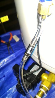
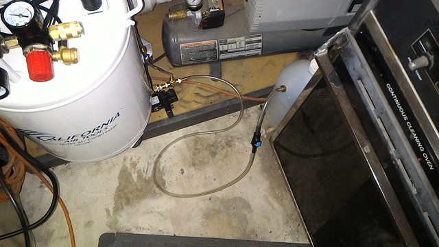
This air compressor was purchased straight from California Air Tools with less than 50hrs at a fair discount and automatically cools the air stream as it exits the Tank by running thru a radiator on top of the tank. This radiator is cooled by some fans to keep the radiator near room temperature causing the water vapor to condense out of the compressed air. The air then passed thru an air/water seperator. This separator causes a significant amount of water to be deposited in it’s reservoir where a tube just drips the water onto the ground (problem #2).
The Air stream is then plumbed to a Activated Alumina desiccant Air Dryer where additional drying is done by chemical reaction. The bottom of this air dryer is also plumbed with a tube which just drips onto the ground (problem #3). The main problem (problem #1); however, that the tank itself needs to be drained periodically as is required for ALL Compressors to prevent the air tank from rusting inside. If I had been purchasing new; I may have just purchased a 10010DACD which as a Automatic Drain Valve installed at the factory… but since this was a discounted unit; I couldn’t get drain valve option. Additionally; the factory charges an additional $150 to cover the installation and plumbing for the Auto-valve; I do not know if CAT will rectify the tubing outputs of the separator and dryer, so this may be an interest read for owners of the more expensive unit.
The result is I need to plumb my own automatic drain valve while making an attempt to tidy up the separator and air drier water outlets so they all exit the machine into a reservoir which can be dumped periodically instead of spraying the water all over my garage floor. This Blog entry is the documentation of what I did in the hopes it can help some other budding laser hobbyists in creating their own Air Assist setup.
I started by researching the concepts behind CAT’s Automatic Drain valve which is pictured here:
As best as I can figure is this is no different from any of the other auto-drain valves available for less than $30 on Amazon. It’s probably even made in China.
I started by researching auto-drain values on youtube where I came across Farmboy’s Garage’s implementation. While complete; it’s kind of scary how he just lets the valve blow water in the the corner of his garage. As he states in a later video; it scares him every time it triggers. My goal is to try to keep all of the water draining into a lidded bucket so the water can be contained and easily dumped as my garage doesn’t have any drains and the compressor is near the interior wall rather than the external garage door.
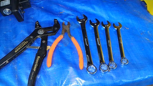
To plumb the cheaper auto-drain valve; I’m going to need to purchase some piping accessories and some vinyl tubing. I came up with this crude napkin sketch before I went to Lowes to “engineer” a solution in their plumbing section. Here’s a shopping list from Amazon if you’d rather purchase as much as you can using your Prime Membership. While this blog entry will focus on adding a auto-drain valve to my compressor; it will probably be very similar to your air compressor. Feel free to reuse as much of this design as you’d like. IF you decide to purchase from your local Lowes; I’ve included pictures of the bags for each step and included the bag part numbers in the shopping list below between ()s.
The total cost of this shopping list isn’t exactly known as the Author has some parts on hand. The plumbing and Auto-Drain valve combined costs about $80 in total. YMMV as costs on these items can vary. Time wise; again it’s tough to say because I had it spread over several days as I waited for parts to arrive from Amazon prime. I estimate you could finish the whole project in an afternoon if you have everything ready to go.
Please note: This retrofit process will likely void the warranty of your CAT air compressor especially if you perform the electrical modifications. The Author of this blog entry is not responsible for any damage you do to yourself or your property.
Duplication of or Plagiarizing from this blog entry is not permitted without written consent from the author and Pinball-Mods.com.
RetroFit the plumbing:
Begin by determining which direction you want the drain valve to go. I’d advise you put the air compressor in its final position and determine which direction the valve assembly should go and drain. The author choose to install his valve assembly going to the right as your looking at the machine. To ease working on the compressor; put the compressor on a work surface on it’s side so you can get easy access to the drain. The Author worked up in the Z direction as he assembled the plumbing.
Remove the stock ball valve on the underside of your air compressor’s storage tank. On my CAT; the factory installed with some clear plumber’s goop to help prevent air leaks. The result is you may have to use a little bit of force to break the clear sealant inside the threads.
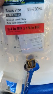
Next; install the 1/4in MIP x 1/4in FIP Brass 90 Street Elbow in the drain hole as pictured:
1/4in street elbow (90deg)
Be sure to wrap the male end of the elbow in teflon pipe tape
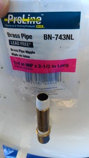
Wrap both ends of the 1/4in MIP x 2-1/2in Long Brass Pipe with pipe tape and install it into female end of the elbow. Use your robogrip or Pipe wrench to make the connection tight.
1/4in street elbow (90deg)
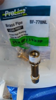
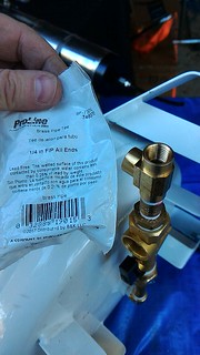
Wrap the male end of the 3/8in MIP x 1/4in FIP Brass Pipe Bushing with pipe tape and install it on the remaining end of the brass pipe. Snug it up with an appropriate sized wrench.
3/8in MIP x 1/4in FIP Brass Pipe Bushing
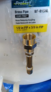
Install the 1/2in FIP x 3/8in FIP Brass Reducing Coupling onto the 1/8″ MIP fitting and tighten.
1/2in FIP x 3/8in FIP Brass Reducing Coupler
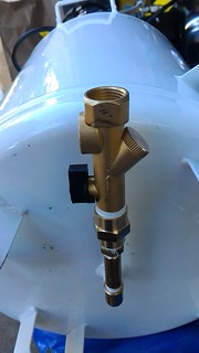
Carefully disassemble the drain valve using the top silver nut and the star washer. This should allow the black plastic body to be removed from the brass assembly. Then you have access to the brass nut holding the actuator assembly to the brass body. Remove it. Note how the device comes apart because you will need to reassemble the valve properly once its completed installed on the machine. Take care as there is a spring and small brass piece inside the brass could get lost. With the black electrical case and valve assembly removed; you’ll be able to install the brass fittings in the following steps.
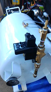
Now thread the drain valve assembly onto the 1/2 FIP coupler from above after pipe tape-ing the male end. Make sure the final tight position of the valve is parallel with the bottom of your tank. The black switch body and actuator should have enough clearance to set just under the tank. Open the assemblies ball valve now.
1/2in Auto Drain Value assembly
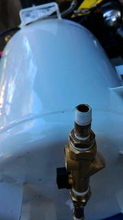
Tape the male end of a 1/2in MIP x 1/4in FIP Brass Pipe Bushing and tighten on the Valve assembly.
Tape both ends of the 1/4in MIP x 1-1/2in Long Brass Pipe and install onto the 1/4″ FIP bushing.
1/4in MIP x 1-1/2in Long Brass Pipe
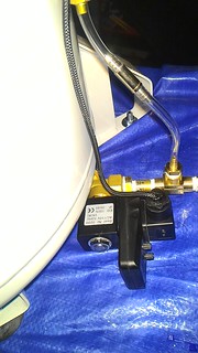
Install the 1/4in FIP All Ends Brass Tee as shown. Ensure the final tight position has the top opening in the direction of the top of the compressor. This will be the inlet of the Problem 2 and 3 filters drains.
1/4in FIP All Ends Brass Tee
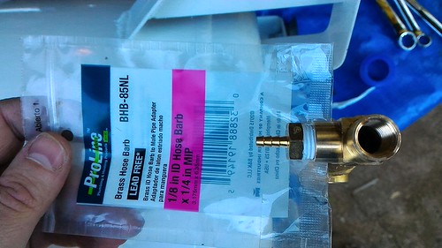
Tape the male thread of the 1/8in ID Hose Barb x 1/4in MIP and install it on the top facing opening.
1/8in ID Hose Barb x 1/4in MIP
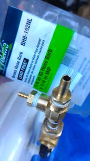
Tape the male thread on the first 1/4in ID Hose Barb x 1/4in MIP and install it on the remaining opening of the tee. This will be the outlet for all water and will eventually go to the bucket.
1/4in ID Hose Barb x 1/4in MIP
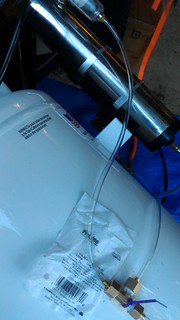
Thread one end of the 0.71ID vinyl tube onto the 1/8in hose barb. Cut the tube off about half way up the side of the tank.
Slip the end of the 0.71 tube into the compression fitting and tighten it onto the bottom end of the Tee. For instructions on installing compression fittings; see this youtube video; however, note that the tee’s compression sleeve is build into the brass nut. Loosen the compression fitting from the Tee and verify the compression fitting is solid. Tape the male end of the fitting and reinstall.
The fitting opposite the drain should be plumbed to the bottom of the Air/Water separator using additional 0.71tube. This separator will have the most volume of water; so it should have the easier path. Remove the existing black tubing on the bottom of the water seperator.
The perpendicular fitting should be plumbed to the bottom of the Chemical Air dryer as large volumes of water are not expected from that part. Remove the existing black tubing on the bottom of the Air Dryer.
0.71in ID Hose routing
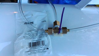
Secure the compression Tee fitting to the side of the tank using a self-adhesive tie down and a zip tie.
1/4in x 1/4in x 1/4in Compression Tee
Cut the 0.71ID tube between the compression tee and the 1/8″ID hose barb at about the halfway mark. This will be the location for the 4mm ID Check Valve. The direction arrow should face the hose barb so that only the water can drain and prevents at pressure air from the tank from back-flowing into the filters.
4mm Check Valve
Reassemble the solenoid valve (reverse of disassembly).
solenoid
ReAttach the electronics to the valve as shown. Note that the “AC in” port of the drain valve should be in the same direction as the 1/8in ID barb (IE facing top of compressor).
valve Electronics
The idea behind the Tee is that water drained from the filters will flow thru the check valve and pool at the outlet of the auto-drain valve. When the drain valve fires; the compressed air+water from the tank will force the pooled water after the valve up and into the bucket will provide later.
We’ll pick up the final bucket assembly after a short break of electrical wiring.
RetroFit the electrical:
Please note: The following electrical retrofit will likely void the warranty of your CAT air compressor. When in doubt consult a licensed electric professional. The Author of this blog entry is not responsible for any damage you do to yourself or your property.
The drain valve operates on 110VAC on the CAT air compressor. MAKE SURE you unplug the compressor from the wall and verify no AC power is present before proceeding. Always make sure the unit is unplugged before continuing work.
There is no clean way of getting switched AC from under the compressor’s switch cover. The Author decided to tap into the wiring harness outside the switch cover. This means that the Auto Drain valve will not always have power and the timer functionality will be effectively disabled unless you are running the compressor at a very high duty cycle. In the Authors case; he expects the auto drain valve to fire each time the compressor comes on; which should be good enough.
You could choose to wire this directly onto an AC plug so the auto drain valve fires as it is intended. This would mean you would have to unplug it each time you power off the air compressor. The Author chose to keep the wiring “inside” the compress as a single unit with one plug to supply power.
The author went overboard on this wiring job; channeling his sleeving powers to make the installation look nice, neat, and professional. He installed some “molex” style connectors as a “y” in the harness to allow the auto-drain valve to be disconnected in the future (or re-wired). This is by no means required; as you could use the same technique CAT used with crimp style connectors. The Author’s method is just one way of solving the problem.
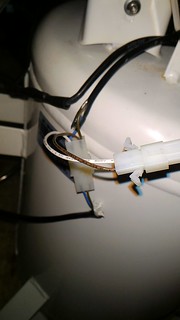
Begin by locating the AC wiring harnesses. The Author checked under the power switch body and identified the black harness. Showing that inside the black harness there was a blue and brown wire which goes to a couple of the AC powered components on the top of the compressor. These were sealed in black heat shrink. Cut the heat shrink away to reveal CAT’s crimped pin connectors.
remove heatshrink
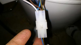
Cut away the existing crimped-on connectors and use a 0.093 2pin connectors with a Y connection (white/brown) in the picture. Basically we’re adding another connection the compressor side of the harness. Crimp the 0.093 male connector for the compressor side and the female connector on the accessory side. The Author used female sockets on the male connector and male pins on the female connector. The idea here is that the pins when disconnected from the main harness cannot easily be touched – lessening the shock possibility.
0.093 AC connector
Crimp on the 0.062″ connector for the new auto-drain valve. Again male connector, female sockets compressor side. Female connector, male pins on the drain valve side.
0.062 AC connector
Route the drain valve ac connection over the top of the compressor, down near the Tee. Disconnect the AC inlet on the drain valve and wire the socket. The author connected the white hot wire to pin 1, the brown neutral to pin2, and the green ground to pin3.
valve electical connection
But… wait Seymour. A 3rd Ground connection? I’m lost… Clearly the AC wiring harnesses of the compressor only have a hot and neutral connection. There’s no third wire. The Author got the ground connection from a screw at the top of the compressor. If you look under the power switch; you’ll see that the ground basically ties into the metal tank. My multimeter check show that any threaded connection will serve as a good ground. More data to follow.
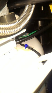
With the drain wired; put a 1/2in strain relief in the hole and route the ac cable up to the same mount used for the Tee and secure it there.
strain relief
Route the drain power behind the handle and secure it with another mount and zip tie.
secure AC
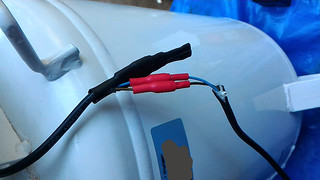
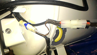
Finally, secure the new connectors onto the other side of the compressor tank. The Author didn’t have large enough heatshrink for the 0.093″ connector; but, he secured it the 0.062″ connector with heatshrink and a zip-tie mount.
secure AC harness
With the electrical complete; you can test the functionality of the auto drain valve. When you first turn on the compressor; the auto valve will fire releasing air out the 1/4in barb fitting. Note your tank will probably be empty when you first fire it up. For that you can watch that the LED comes on Green then goes to red when the valve is closed. You can also let the compressor run for a minute or so and then turn off the compressor with some air in the tank. Then turn it back on and you should hear the drain valve open.
Because the author has his valve fire each time the compressor turns on; he set the time open to the shortest value. This should keep the tank empty of water each time the compressor turns on.
RetroFit Plumbing (continued):
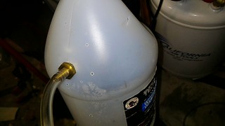
With the electrical complete and tested; it’s time to plumb the exit barb into a reservoir of some type. For this it’s really up to you as to what container you want holding the water. The Author had just used up the last of his Windshield additive so this made a simple, cost effective reservoir. You can use anything you’d like; but we’d recommend something sealed (with a lid) to limit accidental spilling and blow back from the compressed air+water.
On this reservoir; we cut 3 ‘v’shaped holes in the top of the jug above our intended inlet. This is to allow the air to escape but try and contain the water. Failure to put vent holes will likely lead to catastrophic failure of your container. 😀
Identify an inlet location which will be the final 1/4in ID Hose Barb x 1/4in MIP. Wanted the water under pressure to eject downward; so drilled on the top angled surface of the jug. Using a 3/8″ drill bit; drilled the pilot hole and the used the step drill to get right sized hole so the barb could be threaded.
reservoir inlet
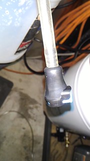
Connect a section of 1/4in ID vinyl tubing to the reservoir.
After about 4-6 inches of tubing; cut. Install the swagelok quick disconnect. On this part; connect the button side which auto closes to the reservoir side. This way; the reservoir remains pseudo-sealed until while you transport it to your dumping location.
Quick Disconnect Coupler
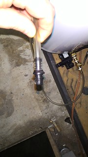
Connect the other end of the coupler to 1/4in ID tubing.
Quick Disconnect Coupler (male)
Finally cut a suitable length of the tubing and connect it to the exposed 1/4in barb on the bottom of your tank.
Final Connection: 1/4″ barb
I have yet to use this system extensively; but I’ll report back if there are any issue and their possible solutions. Hopefully, you have found this blog post useful. If so; feel free to comment below or share on social media.
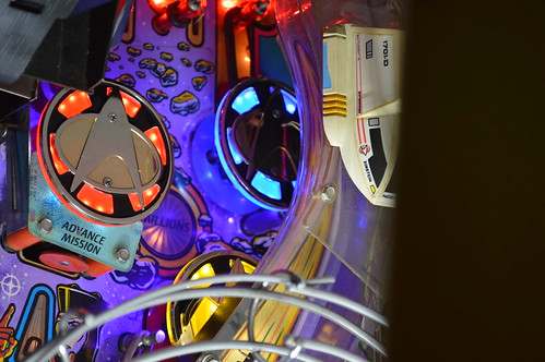
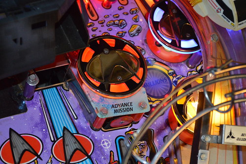
We are pleased to announce the immediate availability of our Star Trek: The Next Generation Popcaps for the 1993 Williams Pinball machine by the same name.
This Popcap kit comes with three high quality Popcaps made of all metal, Zinc Alloy construction and feature a highly polished raised metallic plating for the insignia with a black enamel for the cap’s background. The kit comes with two round caps and one “cut down” cap to fit under the STNG’s beta ramp.
Go from this:
to this:
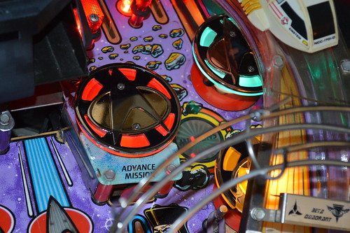
In addition to the metal popcaps; the kit features a set of laser-cut acrylic Undercaps in your choice of colors. The stock kit offers the Undercaps in uniformed colors – IE one red (Command), one yellow (Engineering), and one light Blue (Science). There are also options to go All Red, or all Purple Undercaps to create a specific look for the game. For lighting; the kit comes stock with a 4-SMD #555 comet LED lamps but offers an upgrade to the 11-SMD popbumper LEDs in either Purple, Red, or uniformed colors. We actually offer two versions of the uniformed color 11-SMD configuration – the first being standard Blue:
with the other intended to match Troi’s uniform color: .
Comprehensive, step-by-step installation instructions are included in PDF form on our product page. This PDF also feature modification instructions for the BriteMods’ BriteCap EVO LEDs as they are the recommended LED product to use with these Popcaps.
Check out KnockerLover’s independant review of our Popcaps on Pinside in his STNG Full Title Modding Thread which is a very impressive read on it’s own. He decided to go with an 11-SMD, all purple configuration which looks stunning when combined his re-imagining.
I’ve been eyeing the Dell Latitude 10 tablets for quiet some time. For those that don’t know; they are full PCs running a Dual Core (4 thread) Atom processor. Battery life is ~8hrs. While I really wanted to upgrade my Apple iPhone 4 to a Atom based cell phone like the Lenovo K900; I just don’t have 600 bucks lying around to experminet with (on the ATT network)… so I convinced myself the Dell tablet would be a good distraction for a while.
I bought a refurb unit from the Dell outlet for $360 shipped using a SlickDeals.net 30% off coupon. I went with the non-Esscential version because I wanted the pen digitizer AND the 64GB of solid state memory. The tablet arrived yesterday and so far; I like it. I’ve installed CorelDraw X6 for emergency use while at Techshop.ws.
Because this may be used as a CAD station if there are not spare systems available at Techshop.ws… I think I want the pen interface; sadly the refurb unit did not come with a stylus. Research on the Interwebs led me to the following product: Wacom Stylus for Windows Tablets
Why not buy direct from Dell? Well; honestly – they are running $40-$60 from their site… I want a cheaper alternative.
Update 6/30/14: I’m pleased to report that all three work with the Dell Tablet. Keyboard paired with the tablet without issue and the pen worked out of the box. The case works fine as well; no complaints.
I also went ahead and ordered the K900 a few months ago. It’s now my daily phone; replacing the Apple iPhone4. Nice, thin, and speedy. App compatibility seems spot on. Haven’t installed an app yet from google play which did not work on the Intel(r) Atom(tm)-based phone.
A few months ago; I bit the bullet and got myself a Techshop.ws membership for the Austin/RoundRock location. While not cheap; I expect to make good use of the money spent.
For those that don’t know what Techshop is… in short it’s a “gym-membership” type of place which has over $500k in high tech machinery which the hobbyist can use once they’ve taken the required safety courses. Austin has a Waterjet, 2 shop bot CNC machines, mills, laser cutters, cnc sewing machines, tig/mig/welders, sand and powdercoating , etc.
My first course was Shopbot CNC … Last month I completed Waterjet.
This means I’m now able to use either of these machines.
For the last couple of years; I’ve been wanting to do my own pinball table. Those that know me… will already know the subject matter in question.
About two months ago; I settled on a plan.
Goal:
Create a Star Trek: Mirror Universe pinball table.
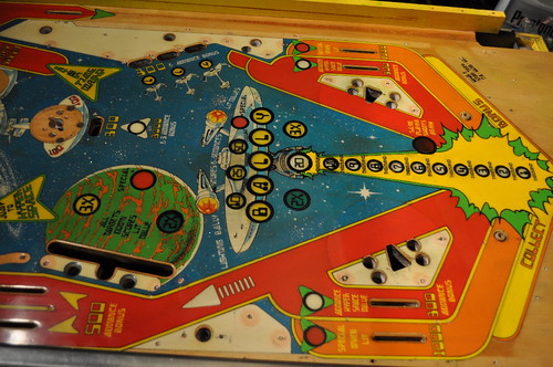
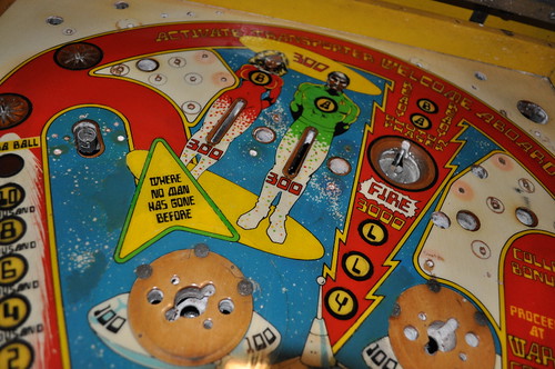
The plan; Scan in a 1979 Bally Star Trek pinball table. Mirror it. And customize it for the mirror universe.
After: (click the picture to get a larger higher rez on flickr)
Yeap; that’s right… the shooter lane will be on the left side (evil grin) and will have a negative feel. What has been done:
Re-colored the playfield; fixed worn areas (in computer). Then flipped the playfield.
Areas changed:
“vectorized” nearly all aspects of the PF.
removed “reversed” text and replaced with Star Trek: series font.
USS becomes I.S.S. Enterprise.
Space Station K0 becomes Battle Station K0
Transporting people become their “mirrored universe” counterparts complete with sashes and skin.
“jump to warp” becomes “Employ Agonizer on Crewman”
“where no man has gone before” becomes:
“Your Mission: Conquer all worlds and civilizations to expand the empire like no man before”
(may be too wordy)
Spelling “bally” becomes “Terra” (Terra meaning Earth. Short for “Terran Empire”; the mirror universe’s “federation”)
Removed same player shoots again language; opting for “shoot again” text over insert.
Drop Target Special becomes Terran Empire logo.
colorized planet with purple glow like the re-mastered series from cbs. Not sure I like it… may go back to original look.
You’ll note that I’ve removed all the switch lanes from the design. The plan is to design a set of hall effect pcbs which replicate functionality without slots in the PF.
I also did the inital CAD work on getting a CNC-ready Playfield.
My next step is to see if I can source some inserts from Pinball Resource. I’ll need to do this before I commit to keeping the same sized inserts as on the original.
I’m curious how Kevin O’Connor would have approached a project like this.
I’ve also been in touch with Kevin at www.tavco.net ; unfortunately – the printer purchased by the Austin / RoundRock Techshop is only 24in wide… and the 4mil pressure sensitive adhesive film I wanted to use only comes in 36inch widths. The only material that comes in 24inch is a non-adhesive roll; meaning I’d have to find some kind of adhesive to attach the graphics to the PF.
Kevin did put me in contact with a local printing company: http://www.aclaustin.com/
whom may have a large format printer which can print directly to the Playfield; which should make it easier to create as I won’t have to “register” and “line up” the graphics to the inserts/table.