Star Trek HAPP CoinDoor Red Alert Indicator

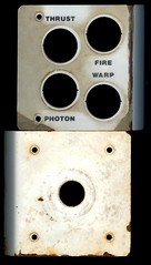
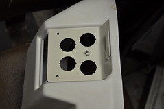
On my Sega Star Trek Captain’s Chair restoration; I had to install a HAPP Coin Door because I’ve been unable to locate an original door. This Restoration is featured at AustinModders.com or KLOV.com for those that are interested in the complete project. Anyway, while installing my custom Coin Door inserts; I decided I wanted to modify the stock HAPP coin “guides”. The stock guides look to be black ABS and well … just don’t do it for me. The stock guides are shown here:

you can see the tiny little square just above the coin slot. This is the area we are going to target with this modification. Once you take apart the coin door; you’ll see guide is a piece of formed black abs:

Once I had this guide out; I measured it using a pair of Digital Calipers and layed it out in Corel Draw X4:

The “nubs” would be laser cut out of 1/8″ Red transparent Acrylic and the blanks would be cut out of black opaque acrylic.

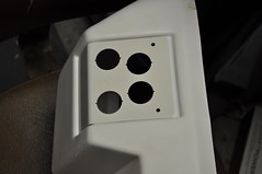
The top of the red “nub” was sandblasted to give it a frosted looks so it’d defuse the light as it exits the nub. When assembled the new guide looks like this:

A 1206 Red LED was soldered into the red acrylic’s pocket with red rework wire attached to the anode and black to the cathode.

I need to drill the coin chute to route the LED’s wires:

and I route the wires out the top side of the chute:

Now that I have the LEDs wired in… what am I going to use them for? Well; I decided I wanted to run the LEDs simular to the Series’ Red Alert indictors I viewed a couple of youtube videos and did some wiki searches; but couldn’t find a “factoid” which gave me the timing of a TOS Red Alert indicator. Therefore; I just decided to make timing which would be pleasing to my eye. If anyone knows for sure a flash target; let me know or leave comment and I’ll figure out the correct timing circuit to flash at that rate.

Anyway; I decided to go with a somewhat simple 555 timer circuit. I have decided to release this  design under to the public under the TAPR Non-Commercial Open Hardware License which indicates:

You may make products based upon this design, provided you do not make more than ten units in any twelve month period for your personal use.

The 555 timer operates in Astable mode governed by R1,R2, and C1.
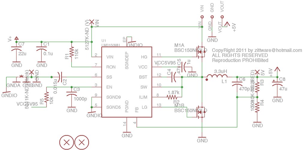
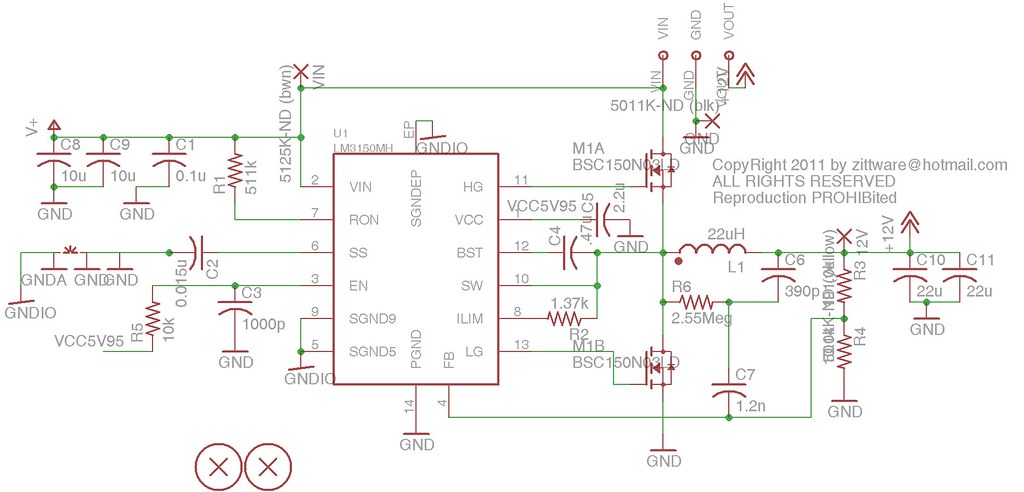
Schematics :


Click to view Red Alert Indicator Schematics in PDF

 The current implementation of the circuit has an “on” time of ~2.6 seconds and an off time of ~1/3 of a second. There is a RC timer made up of R3 and C2 which allows the LED to “wink” into it’s on state. LEDs D1 and D2 are driven by the 2N3904 transistor and wink on at the same time… Rather than do a current mirror; I decided to let D2’s current ~= D1s current given the transistor’s common-base current gain… IE alpha = beta/(beta+1)  which @ ~20mA the 3904’s beta is a minimum of ~90… so alpha is .989 the current of D1. The circuit uses the RST pin of the 555Timer to add additional stability by putting a reset delay on the flipflop in the 555 at ~5seconds. Overkill; proably – but should be very reliable.

The current in the LEDs is controlled by R9 a series resistor intending to limit the current. It was emperically derived using SPICE as a starting point… and then the circuit breadboarded to maximize to 18mA of current flow. D4 is a schottky diode to protect the 555 from reverse wiring mistakes. The LEDs were left unprotected because they and the BJT are diodes … so shouldn’t be impacted by reverse wiring mistakes; additionally, the LEDs voltage drop is already ~2V.. so the 0.1-0.3V voltage drop of D4 might effect brightness.

The PCB is designed as a two layer PCB with through-hole parts on the top layer to enable those less skilled with a soldering iron to build the circuit.


Red Alert LED Fab B Top Layer w/ Silkscreen


Red Alert LED Bottom w/ Silkscreen

 
For those without PCB layout tools; a bare PCB is available from the batchpcb service for under $11. You can purchase the boards from this link:
http://batchpcb.com/index.php/Products/68503

The Bill Of Materials (BOM) of the board is available from Digikey for under $6 (as of the time of this post). A CSV file with the digikey part numbers is here: HappLEDWink_r2.bom.csv

Here’s a package of the materials above as a single download: HAPPBlink_pkg.zip

Here is the the prototype assembled:

Next I needed to mount the PCB inside the coindoor. Since this is a modern replacement HAPP door; I decided to drill and put some #6-32 hex standoffs inside the door. I taped the holes and also added some epoxy to keep the standoffs in place:

I mounted the PCB:

The rework wire is self adhesive; which made it easy to route the led wires back to the PCB and secure it to the reverse-side of the coindoor.

Last but not least; I connected the power to the +5V circuit at the base of the 555 lamp on the coindoor. the lamp circuit on the Sega Star Trek is tied to the +5V PSU… it isn’t 6.3VAC like Pinball Machines.

Here’s the circuit installed and running:

Want to see it in action? Check out our YouTube video:

Custom Coin Mech Reject Art

Having been inspired by Tighe‘s KLOV post on Custom Coin Mech Reject Art – I decided to create some Coin Reject art for my Arcade machines; where applicable based upon his designs. This PDF is provided to you under the TAPR NCL License; which allows you to create and modify up to 10 copies in a 12 month period.

The following Machines are included in the PDF:

  • 1982 Sega Star Trek w/ HAPP CoinDoor (Vector Arcade)
  • 1991 Data East Star Trek: The 25th Anniversery (Pinball)
  • 1993 Williams Star Trek: The Next Generation (Pinball)
  • 2002 TeamPlay Star Trek Voyager (Raster Arcade)
  • 1999 Williams Revenge From Mars (Pinball 2000)

Download the PDF and print without page scaling to get the correct size:

For best results; Print to 8.5×11″ media on a color laser printer.
Tighe prints to standard paper while I experimenting with color laser transparency material.

Download: CoinReject Star Trek n RFM

Enjoy!
Here’s an update to show before / after pics…

As an experiment; I decided to print mine to color laser transparency material I bought by the sheet from Fedex Kinkos. I laser printed it; then coated the back with some summer white plastic enamel I purchased at Lowes. Here’s the result after the white dried:

Here’s the RFM before:

After:

STNG after:

Data East Star Trek: 25th after:

TeamPlay Star Trek: Voyager before:

After:

I’m working on something special for my Sega Star Trek Captain’s Chair… so I’ll post pictures of the inserts when I have an update for my worklog.

Paint matching powdercoat to other colors

During my Star Trek Captain’s Chair Restoration; I found myself wanting to paint match some powdercoat to the existing color of the plastic side panels on the chair.

Please note: Readers are responsible for their own sacrifices to the blood god. Safety first– if you injure yourself implementation of this guide; expect we’ll take no responsibilities. Commentors at Hack-A-Day have indicated that MEK is flammable (as does the label) – so please take the appropriate precautions.

Required materials:

  • Glass or metal mixing vessels  (an airbursh jar works well)
  • Methyl Ethyl Ketone (MEK)
  • A set of Powder Coat colors to mix the colors
  • A paint sprayer… HLVP, Gravity fed, or Airbrush
  • A Panatone(r) Color Cue(TM) or similar device (optional).

Powdercoat using this method appears to be every bit as robust and scratch resistant as normal powdercoat. The author has seen no negative material properties from using MEK instead of a powder coating gun (electrostatic).

For the beginner; Harbor Freight may be a good stop for the primary colors – they usually carry White, Red, Black, and Yellow. Unsure about Green and blue. I also use HF touch up paint guns, HLVP, and airburshes to apply my MEK solutions.  Caswell plating is also a good source for many a color. MEK can be purchase in the paint area of most home improvement stores – I buy mine at Lowes.

I wanted to paint match the powder coat because my chair controls have began to peel and rust. They’ll need to be redone so I wanted them to match the newly retr0brighted side panels.

While the used of the color cue is a good starting place – it isn’t required; you can manually mix colors by eye until you get it right… as you’ll see; I used the color cue to get initial color suggestions (or base colors if you will); then added pure white to bring the color closer to that of the plastics.

I started by measuring the sRGB color of a retr0bright-ed side panel using my Pantone(r) Color Cue(tm) device which I got off of Ebay several months ago and it came up with r246 g230 b198. I pulled these values into the RGB to commercial Tints page at EasyRGB.com. This gave the closest RAL numbers which to match to. I then went to google and did a search for RAL-1013 powder coat which returned a result to powder365.com for their ” Oyster White ” powder coat. Then using the HTML code #F6E6C6
I also used the RGB browser to convert to “RAL Classic” listed six colors with % equivalent matches to my original scanned color.

% 1-?C Color name
96% RAL 1015 Light ivory
94% RAL 1013 Oyster white
93% RAL 9001 Cream
92% RAL 1014 Ivory
90% RAL 9010 Pure white
89% RAL 9002 Grey white

I also did searches for other color combinations and ended up selected the following three colors from powder365.
1lb x RAL 1013 OYSTER WHITE (340/10MIN)
1lb x RAL 7035 LIGHT GREY (340F/10MIN)
1lb x TEXTURED ALMOND (380F/20MIN)

The idea was to put each color on a test piece to see how close to match and pick one which looked the best.

For more information on color matching using the Color Cue; please see Pinball Pal’s Color Cue page.

During my research; I also came across a post to caswellplating.com’s forums which talked about mixing the powder with MEK to “melt” the powder into liquid form for the purpose of correct a blemish on an existing powder coated part. This sparked an idea – why not use the MEK to mix powders together to get an even better color match. I have a quart of MEK in the garage – so it was time to experiment.

I knew the grey wouldn’t really match – it was too grey; so I used MEK to melt it and used a hobby paint brush to apply it to the scrap piece. I then used regular power coating equipment to lay down the almond and oyster for comparison. For the last color; I decided to mix some grey, 2 TSP of pure white (purchased at Harbor Freight), 2.5 TSP of oyster together with a generous helping of MEK to turn the powder to a grey-white “milky” formulation. I applied this with a paint gun:
MEK Test Piece
From Left to Right: RAL-7035+MEK (under thumb), Almond, RAL 1013, and MEKMix

The Right most Grey is “uncured” IE that is how it goes on being applied with a paint gun. Looks fully cured already. and the lines were created with standard blue painters tape. Be-aware – that MEK powder liquid acts just like any paint… it will dry on everything. so protect from over-spray and wear gloves. Unlike the powder form of powdercoat; it can’t just be wiped off of surfaces.

The cool thing about MEK powder-liquid is reportedly it can be used on Plastics and Wood… using low cure temperatures. Ideal for paint matching on cases or other non-metal projects.

With MEK; it looks like one could color match any color given enough patience and primary colors to choose from. Now with this knowledge; it was time to do some actual paint mixing for the purpose of matching the side panels.

I went to work on the control panels:

As you can see the control panels are in need of some TLC. As typical for this machine; the Fire control panel label has begun to deteriorate and is peeling away from the metal. So I removed the label manually – then used Xytol to soak the piece for about 5minutes to soften the label adhesive so it could be removed with a plastic paint scraper. I continued cleaning/soaking the bracket until all the label residue was removed:

Then I sandblasted the bracket w/ ALO2 to remove the rust and other residue. And then finally; I wiped the bracket clean with some clean MEK to remove and remaining dust and oil from the surface.

I then proceeded to powdercoat the underside to the bracket with the Oyster White Powder coat.
For the front; I did an MEK liquid mix as discussed previously. This time I started with a base of 2.5 TSP of Oyster White powder coat and added 1.5TSP of pure white Powder coat. I then mixed with approx 1/4cup of MEK to form a 2% milk-like consistency. I color checked the mixture by using a small paint brush to apply the color to the underside of on of my plastic pieces. This mixture was nearly a spot on match to the plastic so I decided to go with it. I loaded the MEK liquid powder coat to my touch up paint gun

And painted the front / sides with this MEK paint match. Here it is “air cured”:

Once it is dry to the touch / safe to handle (usually about 20minutes); I place the bracket in my powder coat toaster oven for initial curing. during my test runs; I noticed that if you attempt a full cure (400F / 20minutes) with the MEK solution still wet – it will “Boil” the paint leaving rough spots. So I put the piece in the oven at 150F / Warming setting for 10minutes to allow the MEK to evaporate. Then I crank the piece up to 400F for 20minutes for the final cure.

Once the piece cooled to room tempeature; I did a test match against a retr0brighted piece. First; here’s the stock Oyster White (back of bracket):

Notice the slight yellow hue vs the plastic piece.

Here’s the MEK paint match 1.66:1 (oyster to pure white):

I call that a match!

Incidentally; The Color Cue captured an sRGB255 value of 237, 225, 192 for the color matched piece (color code EDE1C0).

Please check out the remainder of the worklog – where I used an airbrush and a laser cutter to create powdercoated labels on the pieces:
1982 Sega Star Trek Captains’ Chair Restoration

Open Source Sega / Gremlin G80 PSU boardset

Over the past couple of weeks; I’ve been designing a replacement G80 PSU for the Sega/Gremlin G80 Vector machines specifically for my Star Trek Captain’s Chair.

I began by using National’s WebBench to design a simulate the 5V and 12V switching PSUs which would replace the linear PSUs on the original board. IMHO; the problem with existing linears is that you’re limited to the Pd of the BJT in the circuit. That BJT leads to a lot of wasted heat in the system. Having said that; I like linear supplies as they are easy to debug and build… for less than 1A of draw.

The Transformer and diode bidges will remain. My intent it to have the board somewhat drop in place of the existing board. I say somewhat; because the power-MOSFETs will need to be bolted to the existing heat sink on both switchers. I’ll probably keep the linears for the negative rails.

I imagine one will have to drill and tap the existing heatsink with some new mounting holes for the mosfets.

Web-bench gave me the following designs:
5V >4A Switcher

12V >2A Switcher

These boards were laid out and put on a single piece of FR4 so they can be assembled as a pair. The design is currently in my BatchPCB shopping cart; waiting for the parent board to complete it’s design phase. Nothing really to write home with regarding these PCBs… I expect the 5V switcher to meet a minimum of 5A… possibly much higher. It’ll likely be limited by the 8A diode bridge on the main parent board. The 12V switcher should meet a min of 2A… probably limited by the 4A bridge on the parent board.

The main parent board is the host for the switching board pairs; and holds the audio amp(s). The main board is currently in development; I’m adding the 12V diode bridge and the final audio AMP.
12V >2A Switcher
Clearly this is an eye-chart schematic. It might be easier to look at the segaSTpsu_rev-99 .

The first notable change is that I’ve replaced the main Audio AMP #1 with a ClassD part from Maxim: MAX9742. This integrated AMP IC should provide specs better than the original discreet amp on the board. It’s configured as a bridge tied load (BTL) targeted for a 23V/V gain with a -3dB frequency of 25Hz. This -3dB frequency and gain was obtained from a spice simulation of the original discreet circuit.

Other notable changes include:

  • Q23 (2N3906) makes “pull down” pulse remover for the CPU board. In the G80 PSU; R23 and D1 make up a pulse circuit which is sent to the CPU board. The CPU board has a 555 timer which implement a missing pulse detector. If a pulse is missed; it puts the CPU into reset. If my theory holds; the 2N3906 acts as a pull down preventing pulses from reaching the 555 timer – which puts the cpu in reset. So if my switching PSUs are not in regulation; this transistor effectively provides a not-“power good” signal to the CPU.
  • U3, U4, and U5 are power good circuits / detectors. U3 is a MAX8215 which monitors the 4 main digital rails to the G80 card cage: +5, -5, +12V, and -12V. These four voltages are “compared” and if in regulation a high is placed on the OUTx lines. These four signals are ANDed together and sent to DIN where it’s “delayed” by ~200mS via C20/R12. This allows the PSUs to stabilize before the CPU is given the “OK” via Q23. U5A and U5B/A1 provide “power good” LEDs for the various power rails – to aid in quick debug of the G80 PSU.
  • U2 provide a local 3.3V linear PSU to power U5 and the pullup on OUT3 (+12V m0nitor). This was done to enable OK12P to drive !SHDN on the ClassD amp. !SHDN cannot have more than +4V driven into it – hence the 3.3V source/pullup. Idea is to prevent premature popping/clicking while the PSU(s) are coming up. The 12V should take the longest to come in regulation and it’s also similar to the VDD/VSS supplies used in the ClassD amp. Additionally !RESET (Dout/U3) drives the “mute” pin of the (SFT / U1) meaning the ClassD amp should remain muted until the “power good” signal is sent to the cpu board.
  • C32/33/L5 (and C27/24/L12) provide a PI filter to reduce vripple into the switching regulators- increasing their stability.
  • I kept Linear Regulators for the lower power rails (-5 and -12) but upgraded the regulators to the National LM2990 as they provide better short circuit protection and slightly more current (1.8A). If desired; one could “in theory” drop in the cheaper/older 79xx series  negative regulators to save costs. They are pin compatible.
  • I’ve put fuses on the +/-12V regulator inputs which are missing from the original G80 design. F6 is a resettable fuse given it’s low power and we need board real estate for other items.
  • Finally LEDs were put in parallel and under the glass fuses on the board. The theory is that if a fuse blows; the LED become a small 10ma current path and the LED lights indicating to the user that the fuse is blown. I neat debug feature if you ask me -hope it works.

I hope to complete the main board design as soon as my upgraded pcb license comes in.
Once I finish the design and validate/test it… I plan to release the design and PCBs via the TAPR open source license.

See a design error? Speak up!

Notes: Enabling NTFS on LG NAS ( N2B1 )

Jotting down some Notes for enabling the LG N2B1 BluRay NAS to read/write NTFS partitioned USB drives using new firmware and the NTFS-3G package.

  1. Flash new N2B1 firmware to enable SSH server so one can get access to the command prompt on the device:
    Tantalus’ N2B1 Firmware
    Author used N2R1 2569t
  2. Enable SSH in the web console and login into the NAS device using a SSH Client.
  3. login as root . See FAQ
  4. if virgin use of apt-get; initialize the repositories using:
    apt-get update
  5. use apt-get to install gcc compiler.
    apt-get install build-essential
  6. apt-get will fail to install libc6 library; use workaround here:

    mv /sbin/init /sbin/init.mv
    touch /sbin/init
    chmod 755 /sbin/init
    dpkg –configure libc6
    apt-get update
    mv /sbin/init.mv /sbin/init

    WARNING: If you execute the first command, you have to execute the last command, before you reboot your NAS-Box

  7. repeat apt-get install build-essential
  8. gcc -v to verify gcc compiler has been installed and is working.
  9. download NTFS-3G from Tuxera.  Author used: ntfs-3g-2010.10.2
  10. untar: tar xvf ntfs-3g-2010.10.2.gz
  11. cd ntfs-3g-2010.10.2
  12. ./configure –prefix=/usr/lib to install to the correct directory. on Author’s system; the system autoconfigured to /usr/local which caused problems during make install.
  13. make
  14. make install as root. or sudo make install
  15. you should then be able to to mount NTFS partitions using:

    mount -t ntfs-3g /dev/sdb1 /mnt/ntfs

Many Thanks to forum.NAS-Portal.org for hosting the information necessary to piece this together.

GTB Black Hole repo-ed fuse cards

While finishing up my Black Hole project; I found the need to replace my rotted fuse cards with some fresh replacments.

Before:

After:

Thanks to Jim (Gott Lieb?) on RGP for helping me figure out the garbled wording. This post has been updated with the fixed WARNING card.

I’ve made the file available in PDF form so Black Hole owners can replace the fuse cards on their machine.

These resulting PDF file is licensed under the Non-Commercial Creative Commons license.

Gottlieb Black Hole Fuse Cards

Gottlieb Open Source PopBumper Driver Board?

I just successfully; built my prototype Gottileb PBDB design and have tested them in my Black Hole Pinball project at AustinModders.com. I have decided to release this  design under to the public under the TAPR Non-Commercial Open Hardware License which indicates:

You may make products based upon this design, provided you do not make more than ten units in any twelve month period for your personal use.

The design include the recommended fixes from marvins u-fix it site including both  Power and Fire LEDs. It also features protection circuitry including a barrier diode and a resettable fuse to try an prevent damage to other devices in your machine. The Logic on this board is Low-Voltage tolerant; so it should operate in situations where +5V is low.

The design uses the more readily available and cheaper TIP120 transistor for driving the popbumper coils.

Schematics :

Click to view GTB PBDB FabB Schematics in PDF

The PCB is designed as a pair; IE you get two boards in the same foot print as the original. I designed it this way to minimize PCB cost, aid in building multiple units, and enabling the boards to be snapped apart after assembly. The board is a two layer PCB with mostly surface mount parts on the top layer to minimize PCB real estate. The TIP120 driver transistor is mounted on the bottom layer again to keep the board size low.

PBDB Fab B Top Layer w/ Silkscreen
PBDB Bottom w/ Silkscreen

For those without PCB layout tools; a set of two bare PCBs are available from the batchpcb service for under $28. You can purchase the boards from this link:
http://batchpcb.com/index.php/Products/44762

The Bill Of Materials (BOM) of a pair of boards is available from Digikey for $10.70 (as of the time of this post). A CSV file with the digikey part numbers is here: A8_PBDB.bom.csv

Here’s a package of the materials above as a single download: GTB_A8_PBDB_pkg.zip

Here are some pictures of the prototypes assembled and installed:

Edit jzitt 11/4/2010 to add batchpcb order link