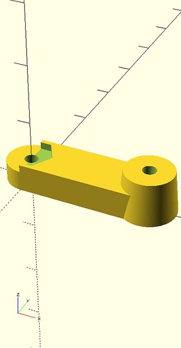
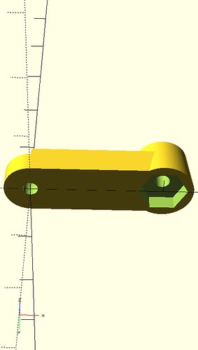
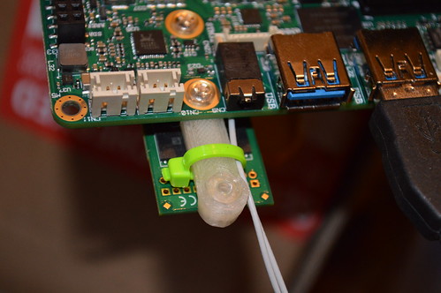
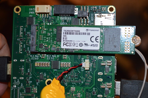
Armed with this new equipment I set about figuring out how to install them on the Udoo X86 board. The board is only setup to support 60mm M.2 drives; so I opened up SCAD and created a quick 3D printed bracket to bridge the gap between the 60mm mounting hole and 80mm M.2 drive’s mounting hole. I 3D printed this using my M3D printer, drilled out the 3D printed #4-40 holes and taped it so I could run some #4-40 polycarbonate screws I had in my modding bins. Any 4-40 screw should work. The bracket I created also has pockets for a #4-40 nut incase you want to drill out the bracket and use a nut. Printing took about 45minutes on my M3D using clear PLA.
A fellow Arcade collector sent me this Private Message a few months ago on the KLOV forums:
I’ve got an old EM Chicago Coin “Shoot Out” gun game. Works great, but came without the sound PCB that generates the gunshot sound. They also made a “Coney Island” game that used the same sound PCB, but I’ve been searching for ~5 to 6 years for a used board with no success.
The problem with the soundcard is it used older End-Of-Lifed (EOL) transistors that can’t be easily found. I offered to help him design a PCB and BOM which would duplicate the sound and provide a “modernized” BOM which could be ordered off Digikey.com. He reported back that after some rework to the pinout; the card worked as expected. As a result; I’ve incorporated the rework (ie corrected the design)… and have provided the materials here for the public to duplicate and use for any older machines which are missing (or has a non-functional board) the EM Gun Soundcard used in these games.
The major changes to this board vs the original are as follows:
The PCB is double sided with large ground plans to aid in noise reduction.
Additional caps are placed on IC1 (LM380) and the Zener diode regulators to help improve the immunity of the circuit to noise. CIC1, C22, C23 – all .01uf.
PCB’s has both a top and bottom silk screen:
Top has values and reference designators to aid in assembly and debug.
Bottom has used edge fingers labeled as well as the legs of the transistors; again for debug.
All transistors were replaced with 2N3904 NPN transistors which are very much still in use today. The single PNP was replaced with the 2N3906.
Test points for the 18V, 12V, 9.1V, and ground rails are provided for easily troubleshooting the voltages on the sound board.
LEDs provided for the 12VAC and 30VAC lines coming into the sound card. Again quick glance that there is at least some voltage going into the sound board.
Although not needed in a real game; two mounting screw holes are needed if you have a non-standard installation.
You may make products based upon this design, provided you do not make more than ten units in any twelve month period for your personal use.
If you agree with the license terms; Schematics and BOM lists are posted here under TAPR/NCL license: Rifle 444-310 Soundboard Package
Ordering should be easy: https://oshpark.com/shared_projects/6GKvZu4s
The boards are $67-ish for a set of 3 PCBs… and they are high quality. Gold plated fingers, two layer, silkscreen on both sides. It’s the cost of doing prototypes. OSHPark usually get the PCBs back to you in about 2 weeks.
BOM Cost from Digikey came to a WHOPPING $17 for one board. My advice is to take the BOM and multiply it by 3 in Excel or some other spreadsheet app. It’s usually cheaper to by 50 or so of the resistors. IE in one qty; they are 8cents… in 50s they are > 3cents. I usually buy 50-100 of each; just so I have them around when I prototype on breadboards and such.
The PCB is very compact; it was done this way to save on the prototype PCB sq inches cost. If you find some of your components are tight; you might try laying them similar to this: http://pcb.bastl.sk/?page_id=50
Here’s a picture of the assembled board:
Rifle Ricochet sounds w/ AMP Fab B assembled
Hope this helps the EM Gun collectors out there. If it does… please drop me a comment letting me know it’s done some good!
My Sega Star Trek Captain’s Chair is destined to be present at the 2012 Texas Pinball Festival. As a result; the game needs to have a FreePlay feature (IE a way for the public to play the game without needing quarters). I know Sega Star Trek has a freeplay rom hack available; however, at this moment, VectorLabs isn’t supplying freeplay roms with their devices. I haven’t spent enough time with the multi-vector boardset to determine how easy/hard it would be to convert to Freeplay. As a result; I wanted a simple inexpensive way to credit up the machine when the user pressed the Start button (1UP).
I toyed with the idea of using a cheap 8pin ATMEL microcontroller; but decided a simple 555 timer could be developed to do most of the heavy lifting. In the end I decided to go with a dual 555 timer (NE556) in a cascaded mono-stable configuration. The circuit features:
PowerOn Reset to “credit up” a single credit when power is applied to the machine. Jumpered feature.
Ability to drive COIN_NO signals
Ability to “interrupt” COIN_NC
Can be alternatively stuffed for AC power supplies (6.3VAC GI circuits in Pinball Coindoors).
Jumper configuration to “disable” circuit.
Barrier Diodes to help prevent “installation error”.
You may make products based upon this design, provided you do not make more than ten units in any twelve month period for your personal use.
Schematics :
Click to view FreePlay 555 Schematics in PDF
The first timer conditions the active low switch connected to J2-3 (1P [aka the start button]). On the Sega vector hardware; this signal is tied high to 5V via a 2.2K pullup resistor. The start button connects momentary grounds at this signal. The Trigger on the 555 timer is also triggered when the voltage at pin 6 transitions below 1/3VCC. D4 protects the cpu board by preventing current from flowing back into the cpu board. This timer “de-bounces” the switch which sends a single long pulse via OUT1 (pin 5). This timing is created by TA = C6*R4 or ~242mS. I’ll explain the function of R5, JP3, D1, and C7 later.
OUT1 drives the “armed” LED to notify the user/debugger that a “start” pulse was received. OUT1 is coupled to Timer2 via C4 and R6. The purpose of these components is to provide a “negative” trigger pulse at the falling edge of Output. Timer2 then drives based upon TB = R1*C1 or ~60mS. This is the coinup signal which is sent to the coin circuit of the arcade machine. 60mS was derived from measurements of my acutal Star Trek Captain’s Chair by dropping a quarter into the slot via an Oscope.
OUT2 (pin9) drives Q2 and Q1 respectively. When not processing “start/coin up signals” Q1 is “active” providing conduction between the CPU Board and the Switch (PNP active when base is low). On the sega star trek; I found that I had to interrupt the NC signal of the switch in the coin door to get the cpu to “detect” a coin from our COIN_NO (J2-4) – Q1 provides this interruption. Speaking of NO, Q2 goes active when OUT2 outputs a high… which drives a “low” to the COIN_NO. In the Vector machine; COIN_NO is pulled high thru another 2.2k resistor and drives the !Set signal of a Set/Reset Latch made out of NAND gates. Incidentally; the NC signal drives the !Reset signal. The Q output of the NAND gate drives the clock of a D latch which drives the interrupt pin to the cpu board.
I promised to talk about the R5/C7 combo. These components control the “poweron” coin up timing. TpwrCoin is a function of U2’s timing and R5*C7 which is basically ~1.2seconds. U2 is a ActiveLow microprocessor supervisor IC. It monitors the 5V powersupply and holds !RST low for about 150mS. This allows the top of R5 high thru a 5.5k internal pullup resistor when the device is non-active. Meaning U2 will drive RST high on each timer after 150ms once the 5V rail is at least within 15% of the 5V target (4.25V). This effectively provides a “credit” signal to the game about 1.2seconds after the power button is pressed (for initial credits). In theory; this circuit can be disabled by removing JP3’s shunt.
JP1 provides a mechanism to “disable” the freeplay circuit. IE virtually removing the circuit from your game. Use this in position [2-3] to disconnect the timers from the bases of the transistors which should return the game to normal operation. IE if you want to start charging people money. I plan to use it to enable money when I take it for charity work.
Please be aware; this circuit still allows the coin shutes to work… even if the circuit is enabled. This was intentional.
The PCB is designed as a two layer PCB with through-hole parts on the top layer to enable those less skilled with a soldering iron to build the circuit.
FreePlay 555 Fab A Top Layer w/ Silkscreen
FreePlay 555 Fab A Bottom w/ Silkscreen
For those without PCB layout tools; a bare PCB is available from the batchpcb service for under $14. You can purchase the boards from this link: http://batchpcb.com/index.php/Products/75967
The Bill Of Materials (BOM) of the board is available from Digikey for $9.02 (as of the time of this post). A bom is included with the schematics PDF above, but An XLS file with the digikey part numbers with the complete package of the materials above as a single download: FreePlay555_pkg
The author’s prototype was built from mostly RadioShack parts he had in his parts bin including the breadboard. He intends to replace this with a PCB from batchpcb in a few months.
Installation note: You need to make sure this circuit used the same voltage rail of your cpu board. The authors’ G08 wiring harnesses did not follow either the Cockpit (which is correct) schematics or the Upright harness (which is incorrect). The J4/P5/p12 harness shows that the cockpit connects the coindoor lamps to the +5V rail at P5 pin6 and pin8. However, The author’s harness had it connected to the -5V rail which is BAD and will prevent the circuit from working properly (and possibly damaging your machine). The upright schematic shows that +5 and -5V goes to the lamps for 10V… also bad.
Either wire up a new +5V signal to this board; or correct your wiring harness to be like the schematics of the cockpit. Seriously – go double check it.
I wired in this circuit into the coin door harness so the board can be bolted to the inside the door. You’ll need to “cut” the NC wire of one of your coin switchs and put this circuit between it at J2-5 and J2-6. Then wire in the NO signal at J2-4. The Start Button goes to J2-3, the +5V rail to J2-1, and Ground to J2-2.
The circuit works as expected in my machine…. providing an inital “Free” credit upon powerup and then providing additional credits each time the start button is pressed (after the game starts). If you want more than one credit; the circuit can be redesigned; or you can press start multiple times during your “inital” game. 😉
I’m fairly sure this circuit can be adapted to any arcade machine. I provided a bridge rectifier stuffing option at B1 to enable “AC” voltage inputs from 6.3V AC. Or Jp2 can be “bridged” with solder to enable 5V to via the D3 shottkey diode. I plan to test this circuit on my Bally Star Trek Pin once I get the PCBs back.
Enjoy… I’ll post more pictures when I get the PCBs back from batchpcb.
For those following my Sega Star Trek Captain’s Chair restoration; I replaced all the bronze plexiglass with some newer Transparent Grey Acrylic which did not have scratches. One of these peices was featured in the Restoration Worklogs at AustinModders.com or KLOV.com where I custom laser etched schematics of the Klingon D7 crusier and the Nomad Probe:
At the time; I predicted that the etch would not show up well once it was installed in the chair:
Sadly; that prediction came true. As a result; I decided I wanted to find a way to lite the etch with LEDs. SeaWolf on KLOV mentioned to me that he planned on lighting his Chair with some red lights to give it a “battle stations” feel while playing… I told him at the time; I’d proably steal his idea … which is the update your reading about now.
To light the Etch; I decided to create a Red Light bar under the custom Black Corner piece I created when I destroyed mine. But before we go there; I had to decide HOW to create the light. I decided I wanted mine to “activate” when a new game was started and then automatically turn off when the game was finished. I don’t have access to the Star Trek source code; so a software hack seemed problematic. Hummm… What’s the next best thing? Audio! With the exception of attract speech from Scotty and Spock; the instructional videos are silent. So I decided I wanted my machine to go into “Red Alert” Mode when real game play audio starts.
The Red Alert Audio circuit was born. 😉 I spent several nights running spice simulations and came up with this circuit which I’m donating to the public under the TAPR Non-Commercial Open Hardware License which indicates:
You may make products based upon this design, provided you do not make more than ten units in any twelve month period for your personal use.
Schematics :
Click to view Red Alert Audio Schematics in PDF
The only IC in the circuit is U1, a dual JFET opamp – TL062P which operates from a single supply at ~12VDC. U1A makes up a 13.5x amplifier to amplify the ~100mV speaker signal from J1-1. The amplifier operates in non-inverting mode; so the gain is derived from 1+R9/R7. R6 is a series resistor intending to limit the loading of the audio amplifier (prevent distorition) and impedance match closer to the that of the 8 ohm speakers present in the upright version of the Sega Star Trek. D1 and D2 provide over/under voltage protection for U1A; limiting pin3 to 12+0.7V and ground (-0.7V) – a real possiblity given the audio amp is powered from a split supply @+/-24V. C2 is a DC blocking cap to prevent our single supply opamps’ bias voltage from loading the sega’s audio amps. R10 provides a high resistance path to our bias voltage of ~6VDC.
The second opamp (U1B) operates in comparator mode; comparing to the voltage divider made up of R4 and R5. V+U1B is (R5*Vcc/2)/(R5 + R4) or 100k*6V/(110k) or 5.46V. If we have no input audio; Pin1 floats above our bias of 6V; forcing the comparator to drive low providing no voltage to the remaining circuitry… effectively an off. Once the amplified input exceeds (6V-5.46V) 546mV; charging current is sent to D3. For those paying attention; 546mV /13.5V/V… means the input voltage at J1-1 must exceed 40mV regularly to charge the capacitor at C1. Empircal evidence on my Chair indicates that “Thrust” alone generates ~100mV at Pin3 of the U1A. Ofcourse your mileage may vary depending on a number of factors including your current volume level.
Once Pin7 of U1B begins to provide a voltage it is channeled to the RC circuit made up of R2&C1. Since the comparator swings between ground and ~+12VDC; it take nearly zero time for the capacitor C1 to charge to full capacity ~R3*C2 or 3.5mS. D3 provides blocking to prevent U1B from loading the RC circuit and R3 provides load resistance to prevent “shorting” the opamp to ground while C1 charges. Once U1B turns off; the RC circuit becomes a voltage source for M3. R2 slowly drains C1 meaning Toff = R2*C1 or ~8.6seconds. This time delay is necessary to ensure the red alert bar doesn’t go off in the middle of a game… IE between Sectors.
R1, Q2, and Q2 make up a BJT Current Mirror with M3 becomming the “on/off” switch for said mirror. When the gate exceeds approx 3.3VDC; M3 turns on conducting R1 to the top of Q1. Since we tied V+ (J2-1) to the 12VDC PSU in the sega G08 Card Cage; We can calculate the reference current into Q1. Iref is (V+ – Q1_VEB)/(R1 + M3_Rds); assume Q1_VEB=0.7V and M3_Rds from datasheet is 5ohm max. Iref is (12-0.7)/(681+5) or 16.5mA. Given Q1=Q2; ILED @ Q2 (J2-2) is 16.5mA; meaning we now have the means to pull 16mA thru up to 5 LEDs. Given my planned use is ~2V super bright Red LEDs; we can fit at most 5 LEDs in the leg of the current mirror before we run out of voltage. Q4 is a secondary Current Mirror “channel” to allow me to drive another 5LEDs… so I now have a means to drive 10 LEDs in the Red Alert Lightbar.
The powersupply for the circuit is made up of D4, C4, and C5. D4 provides a blocking diode incase I screwed up the wiring. C4/C5 provide filtering given the 12VDC source is about 12feet away. D5, R11, and Q3 make up a simple linear regulator to derive the 6VDC (VCC/2) biasing voltage to U1.
Whew! – clear as Mudd? There was some detail there; hope some of it made sense. 🙂
The PCB is designed as a two layer PCB with through-hole parts on the top layer to enable those less skilled with a soldering iron to build the circuit.
Red Alert Audio Fab B Top Layer w/ Silkscreen
Red Alert Audio Bottom w/ Silkscreen
For those without PCB layout tools; a bare PCB is available from the batchpcb service for under $15. You can purchase the boards from this link: http://batchpcb.com/index.php/Products/70379
The Bill Of Materials (BOM) of the board is available from Digikey for under $6 (as of the time of this post). A CSV file with the digikey part numbers is here: RedAlertAudio_FabB_bom.csv
Here’s a package of the materials above as a single download: RedAlertAudio.zip
Here is the the prototype assembled:
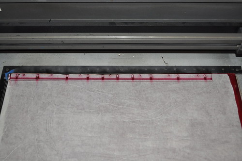
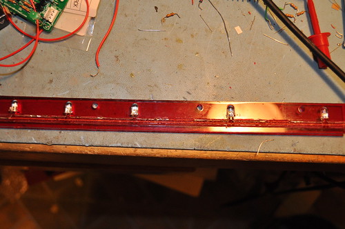
Now I needed to find a way to mount the 10LEDs under the black corner piece. This was done by laying out a 1inch strip of Red Acrylic in Corel Draw and laser cutting said peice:
I decided the LEDs would be wired as a “circuit” on the Red Acrylic. My LEDs are 5mm in size; so these would edge light the 1/4inch red acrylic. I put in 40mil traces in the design which are etched on the laser cutter to give us groves to put the LED leads in:
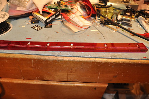
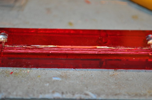
5 of the LEDs were placed on the right side with the Cathode of LED1 at the far left side end. LED2’s cathode is wired to LED1’s Anode repeating until the LED 5’s Anode which is then wired back to the left hand side. When the LEDs touch; they are soldered in place. When they don’t touch a piece of Adhesive red rework wire is soldered between the leads:
The Anode is wired back to the left side by the red rework wire. The Anode of the second 5 LEDs is then tied to the Anode of the first 5LEDs and the cycle repeats in reverse until the cathode of LED1 is at the right most side. It is then tied with a peice of Black adhesive rework wire back to the left hand side. This provides a “single” connection side for all the LEDs.
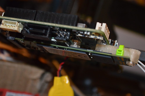
Here’s the finished Circuit on Acrylic:
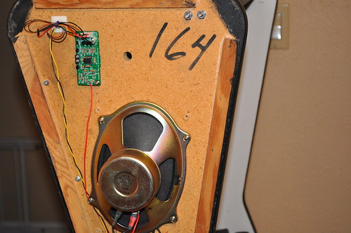
I twisted about 12feet of yellow and black wire together and wired it into the connector on the G08 PSU at the +12VDC lines; it terminates on pin 1 of J1. The LED connections also terminate on J1. I drilled a couple of 7/16″ holes on the right side of the chair near the speaker using the circuit board as a template; making sure not to go all the way thru the side wood – just deep enough for the hex standoff threads. I then tapped these holes with a #6-32 tap; and placed a set of #6-32 hex standoffs in the holes. A couple of #6-32 screws and the board is now mounted at the top of the chair:
I found that I didn’t need to wire the speaker ground from the PCB to the speaker; instead only wired from the + side of J1-1 to the + side of the speaker. A small 7/16″ hole was drilled thru the wood to allow the 3 rework wires to come thru to the PCB. Given rework wire is fragile, small, and solid core; I put about 3″ of stranded 26 gauge wire before the crimp style connector. All of the excess wire was tye-wrap anchored to side of the wood -leaving plenty of “service loops” to enable future changes.
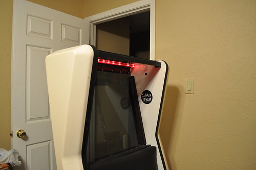
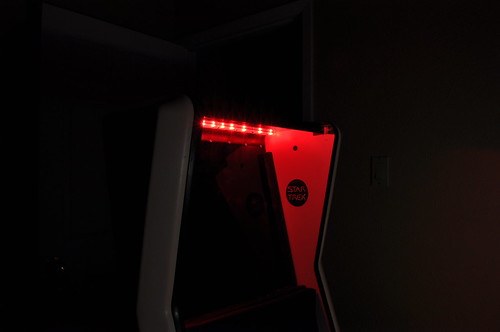
So… was it a success?
Does it Activate as expected?
While the circuit works as expected; it fails to deliver the intended effect of lighting the Window etch properly. Still a cool effect; one I’ll keep… but I’ll need to give the etch lighting some more thought. I’m also going to try and increase the current thru the LEDs by adjusting the R1 reference resistor. The LEDs should be able to handle close to 20mA (package says 24mA max); so the increase in current should brighten them up a bit.
On my Sega Star Trek Captain’s Chair restoration; I had to install a HAPP Coin Door because I’ve been unable to locate an original door. This Restoration is featured at AustinModders.com or KLOV.com for those that are interested in the complete project. Anyway, while installing my custom Coin Door inserts; I decided I wanted to modify the stock HAPP coin “guides”. The stock guides look to be black ABS and well … just don’t do it for me. The stock guides are shown here:
you can see the tiny little square just above the coin slot. This is the area we are going to target with this modification. Once you take apart the coin door; you’ll see guide is a piece of formed black abs:
Once I had this guide out; I measured it using a pair of Digital Calipers and layed it out in Corel Draw X4:
The “nubs” would be laser cut out of 1/8″ Red transparent Acrylic and the blanks would be cut out of black opaque acrylic.
The top of the red “nub” was sandblasted to give it a frosted looks so it’d defuse the light as it exits the nub. When assembled the new guide looks like this:
A 1206 Red LED was soldered into the red acrylic’s pocket with red rework wire attached to the anode and black to the cathode.
I need to drill the coin chute to route the LED’s wires:
and I route the wires out the top side of the chute:
Now that I have the LEDs wired in… what am I going to use them for? Well; I decided I wanted to run the LEDs simular to the Series’ Red Alert indictors I viewed a couple of youtube videos and did some wiki searches; but couldn’t find a “factoid” which gave me the timing of a TOS Red Alert indicator. Therefore; I just decided to make timing which would be pleasing to my eye. If anyone knows for sure a flash target; let me know or leave comment and I’ll figure out the correct timing circuit to flash at that rate.
Anyway; I decided to go with a somewhat simple 555 timer circuit. I have decided to release this design under to the public under the TAPR Non-Commercial Open Hardware License which indicates:
You may make products based upon this design, provided you do not make more than ten units in any twelve month period for your personal use.
The 555 timer operates in Astable mode governed by R1,R2, and C1.
Schematics :
Click to view Red Alert Indicator Schematics in PDF
The current implementation of the circuit has an “on” time of ~2.6 seconds and an off time of ~1/3 of a second. There is a RC timer made up of R3 and C2 which allows the LED to “wink” into it’s on state. LEDs D1 and D2 are driven by the 2N3904 transistor and wink on at the same time… Rather than do a current mirror; I decided to let D2’s current ~= D1s current given the transistor’s common-base current gain… IE alpha = beta/(beta+1) which @ ~20mA the 3904’s beta is a minimum of ~90… so alpha is .989 the current of D1. The circuit uses the RST pin of the 555Timer to add additional stability by putting a reset delay on the flipflop in the 555 at ~5seconds. Overkill; proably – but should be very reliable.
The current in the LEDs is controlled by R9 a series resistor intending to limit the current. It was emperically derived using SPICE as a starting point… and then the circuit breadboarded to maximize to 18mA of current flow. D4 is a schottky diode to protect the 555 from reverse wiring mistakes. The LEDs were left unprotected because they and the BJT are diodes … so shouldn’t be impacted by reverse wiring mistakes; additionally, the LEDs voltage drop is already ~2V.. so the 0.1-0.3V voltage drop of D4 might effect brightness.
The PCB is designed as a two layer PCB with through-hole parts on the top layer to enable those less skilled with a soldering iron to build the circuit.
Red Alert LED Fab B Top Layer w/ Silkscreen
Red Alert LED Bottom w/ Silkscreen
For those without PCB layout tools; a bare PCB is available from the batchpcb service for under $11. You can purchase the boards from this link: http://batchpcb.com/index.php/Products/68503
The Bill Of Materials (BOM) of the board is available from Digikey for under $6 (as of the time of this post). A CSV file with the digikey part numbers is here: HappLEDWink_r2.bom.csv
Here’s a package of the materials above as a single download: HAPPBlink_pkg.zip
Here is the the prototype assembled:
Next I needed to mount the PCB inside the coindoor. Since this is a modern replacement HAPP door; I decided to drill and put some #6-32 hex standoffs inside the door. I taped the holes and also added some epoxy to keep the standoffs in place:
I mounted the PCB:
The rework wire is self adhesive; which made it easy to route the led wires back to the PCB and secure it to the reverse-side of the coindoor.
Last but not least; I connected the power to the +5V circuit at the base of the 555 lamp on the coindoor. the lamp circuit on the Sega Star Trek is tied to the +5V PSU… it isn’t 6.3VAC like Pinball Machines.
Here’s the circuit installed and running:
Want to see it in action? Check out our YouTube video:
Having been inspired by Tighe‘s KLOV post on Custom Coin Mech Reject Art – I decided to create some Coin Reject art for my Arcade machines; where applicable based upon his designs. This PDF is provided to you under the TAPR NCL License; which allows you to create and modify up to 10 copies in a 12 month period.
The following Machines are included in the PDF:
1982 Sega Star Trek w/ HAPP CoinDoor (Vector Arcade)
1991 Data East Star Trek: The 25th Anniversery (Pinball)
1993 Williams Star Trek: The Next Generation (Pinball)
2002 TeamPlay Star Trek Voyager (Raster Arcade)
1999 Williams Revenge From Mars (Pinball 2000)
Download the PDF and print without page scaling to get the correct size:
For best results; Print to 8.5×11″ media on a color laser printer.
Tighe prints to standard paper while I experimenting with color laser transparency material.
Enjoy! Here’s an update to show before / after pics…
As an experiment; I decided to print mine to color laser transparency material I bought by the sheet from Fedex Kinkos. I laser printed it; then coated the back with some summer white plastic enamel I purchased at Lowes. Here’s the result after the white dried:
Here’s the RFM before:
After:
STNG after:
Data East Star Trek: 25th after:
TeamPlay Star Trek: Voyager before:
After:
I’m working on something special for my Sega Star Trek Captain’s Chair… so I’ll post pictures of the inserts when I have an update for my worklog.