On Feb 15, 2023; ingo333 of Pinside released a bug fix update to the Williams Star Trek Pinball machine from 1993. You can download his rom patcher from: his proton drive for free. Included in the change list is the incorporation of the Lamp matrix patch to make it it more compatible with LEDs and this feature is controlled by an Feature Adjustment in the game’s settings. There are several other improvements including randomized shuttlecraft caves which are clearly documented in the STNG_LX8.pdf inside his archive.
In celebration of their work; I created a set of EPROM labels to cover the eprom window. I’ve decided to release the labels for free personal use. Enjoy!
Unlock Backglass and place in a safe place to prevent breakage. Key for the lock should be in the coin door of your machine.
Open service door and locate CPU board on left hand side. You shouldn’t need to remove speaker panel to install new rom.
Remove AA batteries to drain game settings. The reason why is explained in Chapter 4 (Troubleshooting) of their manual.
Using a chip puller; carefully remove the existing rom on the CPU board. Note the orientation of the existing rom. It should be with the notch facing the right hand side of the game. Set old rom aside incase you want to back out this upgrade.
Carefully install the new LX-8 rom chip in the same orientation. The notch should face the right hand side of the game. Watch during installation to make sure no pins are bent as the rom is installed in the socket. The pins can bend under the package so best to do it with a flash light.
Inspect newly installed rom to insure no pins are bent and that you didn’t offset during install.
Re-install batteries. We’d suggest taking the time to install a fresh set so that you don’t have the batteries leak.
Verify the notch orientation a final time.
Once you’re sure it’s installed properly; power up the game. You should be greeted with a “Factory Reset” message.
Open coin door and enter service mode using the buttons. You should see LX-8 displayed on the DMD. Adjust settings as desired based upon STTNG_LX8.pdf manual in the proton drive archive.
Close service door, re-install backglass, and return the backglass lock to the coin door.
In celebration of Chad’s work; I created a set of EPROM labels to cover the rom files. I’ve decided to release the labels for free personal use. Enjoy!
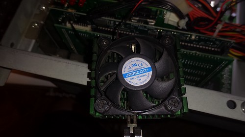
When I first got my Revenge From Mars from a local Pinhead; the fan was clogged with dust and grime. At the time; I simply cleaned the fan, removed the sticker, and added some oil to the bearings. This lasted about 3months before the fan began to make some horrible noises because the bearings were shot. I “lived with it”; but it remained on my todo list.
For years; I had watched threads about Pin2k in Pinside… always feeling a little guilty I had not eliminated the risk that my CPU fan would die… overheat the cpu… and put my RFM in jeopardy of force converting to NuCore or Pinbox. Today was the day I vowed to resolve that noisy fan.
First; I did not want to buy NOS (new old stock) of some 50mm fan made back in 2000 or some china knockoff that wouldn’t last another 18 years. I wanted a high quality fan with very little noise; but a good performer. I’ve grown to like the Noctura brand of fans because they aren’t cookie cut china knock offs. Noctura does not sell a drop-in-replacement for 50mm fans. Going smaller usually means less air flow with a higher “whine” because the fan blades have to go much faster to move more air. So I decided that I was going to try and use the NF-A6x25 FLX 60mm fan:
and build an adapter to fit the larger fan over the existing heatsink. This blog entry documents my solution, provides a TAPR/NCLed DXF for my adapter, and links to a Shapeways implementation of my adapter my fellow pinball enthusiasts to use.
First, I removed the CPU box from my RFM and pulled out the existing CPU heatsink: Stock Pin2k CPU Fan/Heatsink
Once I had the CPU heatsink free; I unscrewed the old FAN from the heatsink. This was done for two reasons;
I need the heatsink to take caliper measurements in order design a 60mm to 50mm bracket.
Eventually; I’d toss the worthless 50mm fan – but wanted to keep it incase I couldn’t find a working solution.
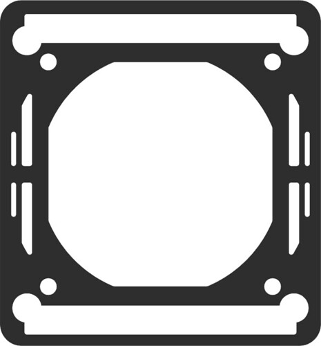
Obviously; the 60mm fan wouldn’t fit within the 50mm cavity of the heatsink; so I knew I wanted to use some 1/4inch clear Acrylic as an “adapter”. I went into qCAD resulting in a DXF file which I could then send to my laser cutter. I wanted to reuse the 50mm fan/heatsink screws and the 4 qty Vibration-Compensators provided in the Noctura kit. My second proto resulted in success and looked like this: 60 to 50mm Fan Adapter
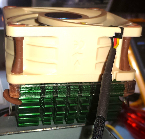
Reusing the 4 qty 50mm countersunk heatsink screws; I attached the clear acrylic bracket to the top of the heatsink. Then I put the 4 qty Vibration-Compensators provided in the Noctura kit thru the acrylic bracket and into the NF-A6x25 fan. The whole assembly fit together quiet nicely. 60mm Fan Adapter – Test Fit
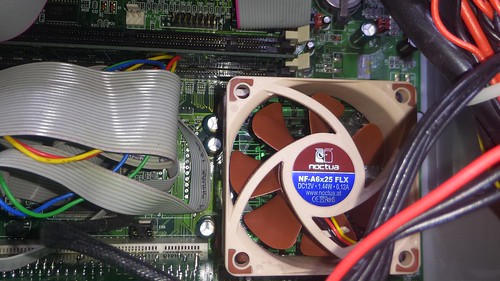
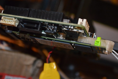
I carefully; reinstalled the fan-sink combo back onto the cpu and socket. This was a little tricky because the 60mm fan is bigger; but as you can see the whole contraption fits well: 60mm Fan Adapter – Motherboard Install
Conveniently; my Pinball 2000 motherboard had a FAN header right next to the cpu socket; so I simply attached the CPU fan’s 3pin PWM connector to that unused mobo connection: 60mm Fan Adapter – Fan Header
I powered up the Pin2k system on my bench with both the original and the new fan connected. !That old fan really needed to be replaced! This new fan is ultra quiet; I don’t think you can hear the fan over the PSU fan even when the box is open. You won’t be able to hear the fan at all when its in the backbox behind the backglass. Success!
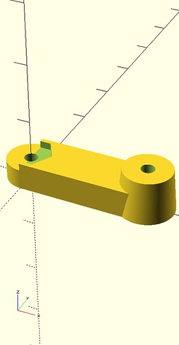
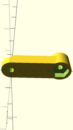
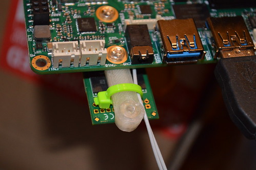
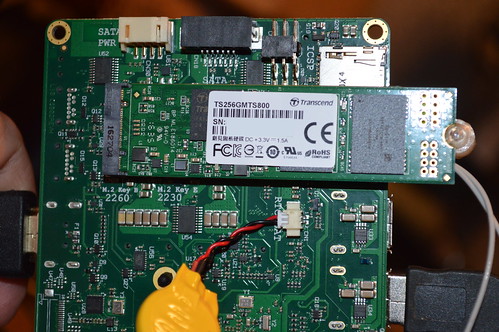
Armed with this new equipment I set about figuring out how to install them on the Udoo X86 board. The board is only setup to support 60mm M.2 drives; so I opened up SCAD and created a quick 3D printed bracket to bridge the gap between the 60mm mounting hole and 80mm M.2 drive’s mounting hole. I 3D printed this using my M3D printer, drilled out the 3D printed #4-40 holes and taped it so I could run some #4-40 polycarbonate screws I had in my modding bins. Any 4-40 screw should work. The bracket I created also has pockets for a #4-40 nut incase you want to drill out the bracket and use a nut. Printing took about 45minutes on my M3D using clear PLA.
A fellow Arcade collector sent me this Private Message a few months ago on the KLOV forums:
I’ve got an old EM Chicago Coin “Shoot Out” gun game. Works great, but came without the sound PCB that generates the gunshot sound. They also made a “Coney Island” game that used the same sound PCB, but I’ve been searching for ~5 to 6 years for a used board with no success.
The problem with the soundcard is it used older End-Of-Lifed (EOL) transistors that can’t be easily found. I offered to help him design a PCB and BOM which would duplicate the sound and provide a “modernized” BOM which could be ordered off Digikey.com. He reported back that after some rework to the pinout; the card worked as expected. As a result; I’ve incorporated the rework (ie corrected the design)… and have provided the materials here for the public to duplicate and use for any older machines which are missing (or has a non-functional board) the EM Gun Soundcard used in these games.
The major changes to this board vs the original are as follows:
The PCB is double sided with large ground plans to aid in noise reduction.
Additional caps are placed on IC1 (LM380) and the Zener diode regulators to help improve the immunity of the circuit to noise. CIC1, C22, C23 – all .01uf.
PCB’s has both a top and bottom silk screen:
Top has values and reference designators to aid in assembly and debug.
Bottom has used edge fingers labeled as well as the legs of the transistors; again for debug.
All transistors were replaced with 2N3904 NPN transistors which are very much still in use today. The single PNP was replaced with the 2N3906.
Test points for the 18V, 12V, 9.1V, and ground rails are provided for easily troubleshooting the voltages on the sound board.
LEDs provided for the 12VAC and 30VAC lines coming into the sound card. Again quick glance that there is at least some voltage going into the sound board.
Although not needed in a real game; two mounting screw holes are needed if you have a non-standard installation.
You may make products based upon this design, provided you do not make more than ten units in any twelve month period for your personal use.
If you agree with the license terms; Schematics and BOM lists are posted here under TAPR/NCL license: Rifle 444-310 Soundboard Package
Ordering should be easy: https://oshpark.com/shared_projects/6GKvZu4s
The boards are $67-ish for a set of 3 PCBs… and they are high quality. Gold plated fingers, two layer, silkscreen on both sides. It’s the cost of doing prototypes. OSHPark usually get the PCBs back to you in about 2 weeks.
BOM Cost from Digikey came to a WHOPPING $17 for one board. My advice is to take the BOM and multiply it by 3 in Excel or some other spreadsheet app. It’s usually cheaper to by 50 or so of the resistors. IE in one qty; they are 8cents… in 50s they are > 3cents. I usually buy 50-100 of each; just so I have them around when I prototype on breadboards and such.
The PCB is very compact; it was done this way to save on the prototype PCB sq inches cost. If you find some of your components are tight; you might try laying them similar to this: http://pcb.bastl.sk/?page_id=50
Here’s a picture of the assembled board:
Rifle Ricochet sounds w/ AMP Fab B assembled
Hope this helps the EM Gun collectors out there. If it does… please drop me a comment letting me know it’s done some good!
I really enjoy my Stern Star Trek LE Pinball machine… But one of the things which has bothered me on the machine was the way the USS Vengeance shines it’s bright blue Nacelle LEDs right in the eye of the player.
This simple mod aims to correct that. I knew I wanted laser cut some blue acrylic pieces to help defuse the LEDs; so I consulted google images to give me some ideas what the Nacelles were suppose to look like:
Without redesigning the whole Stern Nacelle; I decided a piece set about 1/4″in into the nacelle would be closer to film accurate. Also; in a couple of the google images; the Bussard collector looked more cylinder shaped; so I figured a deep etch in the back side of the plastic would be ideal. Here’s what my first prototype looked like in CorelDraw:
USS Vengeance Nacelle Prototype Peices
I then proceeded to Techshop.ws and laser etched/cut these pieces out on some 1/8″ Blue acrylic.
To remove the Nacelle; simply remove the top two philps screws holding the Nacelle to the ship assembly. Then remove it… On my ship; Stern was rather liberal with the hot glue; so I had to work the nacelle off by pulling the sides of the nacelle from the hot glue. The Blue LED is attached to the ship assembly; so you shouldn’t have to worry about it coming loose.
When I got home; I used some plastic epoxy to glue the piece into the left nacelle. This piece is to be position just past the flat ridge in the nacelle:
USS Vengeance Nacelle
Here’s the Bussard collector installed with a little epoxy:
USS Vengeance Bussard collector
NOTE: the curved etch faces the rear of the Nacelle (etch toward LED)
In my case I found it a little easier to bevel the sides of the pieces with a file so the sides of the plastic pieces would make better contact with the sides of the warp nacelles. I put some epoxy on the sides of the piece and on the little round nub at the top of the nacelle so the piece can’t be shaken loose during the Vengeance battles.
So; How’d it turn out? I only modded the left side (right in the picture) and took this picture:
USS Vengeance Mod
A close-up Before and After:
USS Vengeance Mod Before & After
Want to do this yourself? Have access to Acrylic and a Laser Cutter? Great; I’ve decided release this design to the public under the TAPR Non-Commercial Open Hardware License which indicates:
You may make products based upon this design, provided you do not make more than ten units in any twelve month period for your personal use.
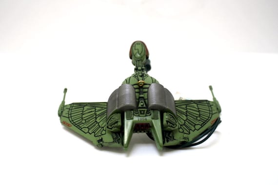
I recently purchased a
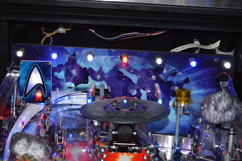
1994 Hallmark Star Trek Klingon Bird of Prey from a fellow Pinsider. This Ornament came ready to install into my 1996 Williams Star Trek: The Next Generation Pinball machine. However before I installed it in the machine; I wanted to make further modifications to the item. My previous installation had installed a die-cast
2005 Corgi Klingon Bird of Prey
for which I’d followed the recommended installation of putting the incandescent light bulbs under the ship:
Before – incandescent light bulb sockets- ICK!
Immediately upon this installation; I knew it wouldn’t do… but I waited several years until I got one of the hallmark ship mods. I decided back then that I was going to put some Electroluminescent panels under the wings… but then came to my senses that the EL panels loose their brightness rather quickly. So; after getting the Star Trek: Mirror Universe pinball machine to a Phase1 complete state; I returned my attention to this mod. I decided this time that I was going to use superbright surface mount LEDs to replace the light bulbs and their bulky sockets.
I started by researching the type of LEDs. A Digikey search came up with some super brights; relatively cheap but with a lot of light output. I figured I could fit about three of these LEDs under each wing; so I began the design phase of the project. I started by doing a pencil rub of the wing’s paint job. This gave me an approximate size of the PCB I needed under the wing. I scanned this pencil rub into the computer and vectorized it into a PCB using the technique posted here. With the PCB outline created; I proceeded to create the schematic of the LED board. I made a design choice to rectify the 6.3VAC GI power rail so that polarity wouldn’t matter during install. I also decided that I’d use a BJT current mirror to light the first LED and drive 20mA thru it. Then use the second leg of the current mirror to drive the remaining two LEDs. To ensure stable voltages/currents; I put a 3.3V LDO regulator and some caps on the first leg to try and keep the brightness from flickering with the 120Hz FWB power rail.
You may make products based upon this design, provided you do not make more than ten units in any twelve month period for your personal use.
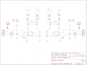
If you agree with the license terms the resultant schematic is posted here under TAPR/NCL license:
STNG KBOP LED schematic
You can buy the bare PCBs from OSHPark from here. Total cost to build this board in single unit quantities as of 6/15/2014 was $14.55 / a pair of boards.
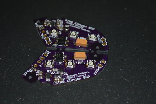
The entire project package is here: STNG_KBOP TAPR Package
It contains the schematic, NCL license, Bill of Materials.
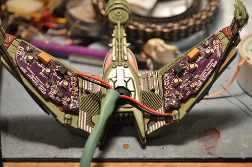
This project requires SMT soldering skills so be prepared. I used a syringe with solder paste to populate the PCBs then used a skillet to reflow the solder. Here’s the assembled PCBs:
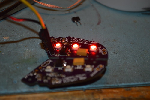
Then I assembled tested the circuit first with my 5V bench supply; then with a 6.3VAC transformer from RadioShack:
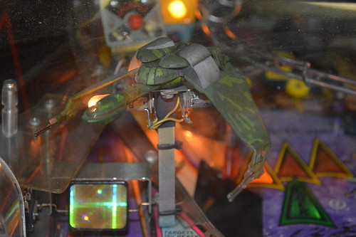
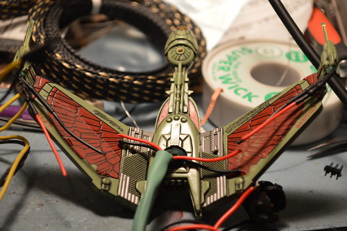
With the boards tested; I began refitting the Hallmark KBOP mod which looked like this:
I removed the green heatshrink hiding the LED wing guns and cut the red & black wires as I had recreated the wires in the PCB and had embedded the resistors hidden under the black heatshrink near the guns:
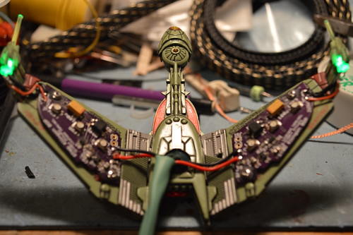
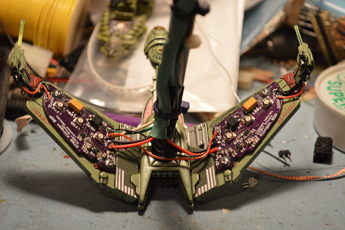
Originally and in the PCB file; I had decided that I wanted to use 2 qty #0 self taping screws to hold the PCBs in place. These were speced at McMaster Carr as #94209a005; but I didn’t want to pay for S&H for that single box of 50. Instead I drilled out the holes a little larger and used #2-56 @ 3/16 of a length. I carefully marked drilled the wings of the KBOP and taped them with my #2-56 tap set. You MUST be careful here not to drill through the wings. Here’s the PCBs mounted:
I then proceeded to solder the cut GI wires for the wing guns to the Jin connections on the PCB. I also connected the Guns to the JWing connection at the edge of the PCBs with a short piece of red rework wire after removing the inline resistors at the LEDs. I secured the electrical connections at the gun LEDs with some liquid black electrical tape:
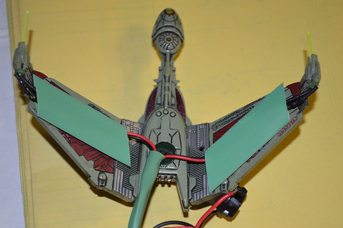
I then proceeded to attach the GI connection from my machine along with the bracket. Reusing the older wireing harness as desoldered from the bulb socket assembly made sure the under wing LEDs lit in the same was as the bulbs:
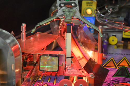
With that the modification of this mod is complete. Here are some mandatory money shots to encourage you to do the same to your machine:
Overall I’m very happy with the results; the Red LEDs really light up the Playfield and I do not have to look at those light bulbs any more. The only thing I noticed with this mod is that my machine doesn’t seem to give me enough voltage at the GI connector to fully lite the two LEDs on the second leg of the current mirror. I think this is because the STNG controls GI; which means there is an extra silcon device between the 6.3VAC transformer and the GI lamps. This is evident when running the shuttle craft missions when all the PF lights are of in this video mode. In a future revision of this mod; I might try directly hooking the second leg of the current mirror straight to the GI input (not FWB rectified) to see if I could coach more voltage across these two LEDs in series.
This PCB obviously fits the 1994 Hallmark ornament seen here and it also seems to fit the Corgi 2005 Klingon Bird of Prey also used in modding these machines.
If you’ve been following ColorDMD‘s updates on Pinside; you proably already know that ColorDMD is currently working on color DMD dots for the Stern Star Trek Pinball Machines. Several months ago I helped formalize plans for an adapter plate for the Stern Star Trek Premium/LE machines.
This DIY mod will allow you to install a Color DMD in a machine without modifying the stainless steel speaker panel. This Adapter completely covers the studs on your metal speaker panel; thereby preventing the studs from scratching or cracking your $400 ColorDMD (LCD) display.
Madaracs on the KLOV forums was kind enough to loan me his Sega Captain’s Chair CoinBox for measurement of the dimensions. With his coinbox I was able to modify the preliminary plans I had posted to my Captain’s Chair Restoration.
You may make products based upon this design, provided you do not make more than ten units in any twelve month period for your personal use.
If you agree with the license terms and are interested in the coinbox plans; they are here:
Sega Star Trek Captain's Chair CoinBox Plans (PDF)
Thanks to Muel and Madaracs for the help enabling these plans. Now all I need to do is gain access to Austin’s TechShop to waterjet me some material from these plans.
Almost a year ago I posted in my Star Trek Captains’ Chair worklog that I intended to modernize a old XY Pattern Generator design on the interwebs. Many of the guys on VectorList provided valuable insight into the interworkings of the circuit… and provided many layers of helpful advice.
The result was a working prototype board from BatchPCB.com as a dual sided board. Surface Mount ( yes; I can hear the screams of horror ) as I wanted to minimize PCB size and thereby cost.
There were several key learnings that I’ve noted while building, debugging, and using the Vector Pattern Generator. These learning were as follows and have been incorprated into the FabB design:
The clock generator circuit (3.578MHz xtal) and U1ABC was not “locking”. This was due to the buffered logic of the newer 74HC* logic. Some research on the internet indicated I needed a 150pf cap from pin1 U1A to ground to allow the clock generator to exite enough to lock.
The -12V buck converting power supply wasn’t outputing the correct voltage. It’d start out at ~11V…. the drop to ~5V over several minutes. On my debugged board; shorting R26 (10meg ohm) allows the -12V to become rock steady at -11.8V. Unsure here; the Maxim EE sim was very specific on the 10meg ohm value… but the maxim datasheet indicated two modes for VL to operate in. So for now will error on the practical side.
The 5V regulator did not have enough copper to heatsink to. FAB B has a large 5V copper heatsink built into the board for the linear regulator. For my prototype; I thermal epoxied a small heatsink from a old motherboard onto the top of the regulator to give it some thermal sink.
The Linear POT datasheet was missing details regarding the LED side of the POT. One hole was off and was moved to match the device.
I also included the following “Nice to Haves” into the FabB design:
Retrofitted EPROM sockets to enable A11 for a 27C32 eprom(s)… allowing for more user designed test patterns. NOTE: A11 is hardwired to high to match 2716 eproms configurations. No clock/decode is provided for A11. Future FabC work if a solution can be found.
At this time you can use either 2716 or 2732 eproms in this design.
Renamed topside adj pots to indicate X and Y.
Converted to 3pin jumpers so the jumpers can be mechanically sound when output swing is not shorted.
You may make products based upon this design, provided you do not make more than ten units in any twelve month period for your personal use.
If you agree with the license terms and are interested in the FabB schematics; they are here:
Vector Pattern Generator: Fab B Schematics(Click here to open as PDF)
For those without PCB layout tools; a bare PCB is available from the batchpcb service for under $65. You can purchase the boards from this link: http://batchpcb.com/index.php/Products/91905
The Bill Of Materials (BOM) of the board is available from Digikey for $75.51 (as of this post).
A bom is included with the schematics PDF above, but An XLS file with the digikey part numbers with the complete package of the materials above as a single download: XYpatternFabB_pkg.ZIP You will need to source your own 2716 or 2732 EPROMs as Digikey does not carry them. You’ll also need to source your own 14-16VDC wallwort … you may already have a donor in your parts bin leftover from a defunct piece of equipment.
ROM images for the EPROMs can be downloaded from several sources. Hint: Do a search for XY ROM images .zip in Google.
Use the ROM images as-is for 2716 EPROMs. For 2732 EPROMs; just dup the roms using the following dos commands (as an example):
copy /B X.BIN+X.BIN x32.bin
/B is important as it tells copy that the files are binary, not ASCII files.
The Author is still using the FabA prototype; he has not yet built FabB so YMMV. The changes from FabA were relatively simple; so building these should be a low risk.
The active components (switches, linear pot, adjustment pots, jumpers, and video connector) are all populated on the reverse side. This will allow me to put the board on standoffs and a acrylic top on the device to protect it from dust/flying multimeter/scope probes.
The board is still quite big even with the surface mount components measuring 5.1×3.9in tall. By far the largest parts on the board are the EPROMs… maybe one day I’ll figure out how to move the EPROMS into a single EEPROM device and surface mount it.
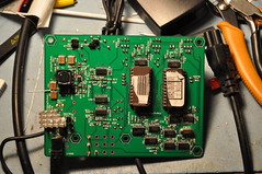
So; what does the Fab A prototype look like?
Click to see higher rez pictures
Vector Pattern Generator: Primary side
This is the primary side; which faces the workbench in normal operation.
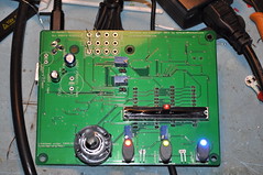
Vector Pattern Generator: Secondary side
This is the secondary side. It becomes the “top” of the unit so the user can adjust settings and the like.
Please Note: This implementation is not perfect… there are some issues with the vector generation that I haven’t been able to debug. The imperfection does not really limit the functionality; as you can easily converge and debug a vector monitor with the vectors. I am hopeful someone can help me debug the issues so we can release a better project long term.
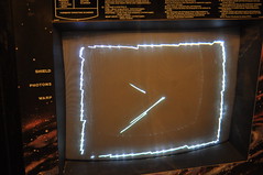
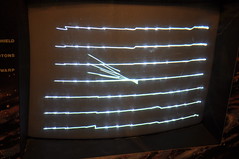
Overall the generator worked quite well as I was able to get my ElectroHome G08 monitor converged.
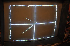
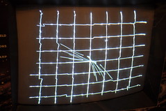
Vector Pattern Generator: Box pattern
I can’t explain the center vectors… nor why the lines become squiggly. They don’t move; it’s always that way.
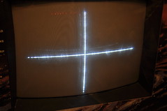
Vector Pattern Generator: Cross pattern
Strange that the site pattern doesn’t seem to suffer from odd vectors.
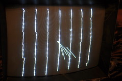
As you can see; the generator works well enough to converge a vector monitor…
At this point I’m not sure if the odd vectors / none straight vectors are the result of a software problem (EPROM images) or a hardware problem.
It’s possible the software isn’t reacting well with the faster hardware (HC logic, better opamps); but unsure.
Things I still need to do [if I ever find the time]:
check the +12V portion of the buck converter. Right now I’m using the backup +12V linear regulator (U9).
Create an enclosure to house the unit.
Figure out how to clock A11 to enable full 2732 support; thereby more test patterns.