For years I’ve been limping along with a very noise older model Air compressor for my Modding needs. Recently; I upgraded from a Universal Laser 25E laser to an Epilog Legend 24TT laser cutter. The former could be outfitted with Air Assist; while the latter came pre-plumbed for Air assist. The issue is that the Air Assist works best if the lens doesn’t get splash back form the Air assist when it contains water.
Air compressors work by compressing the gas of surrounding air which contains water vapor. This water vapor leaves the compressor very hot along with the compressed air stream. As it sits under pressure; the water vapor condenses as it cools leaving water in the air lines. A properly configured Air Assist needs to remove that water vapor so it cannot exit the assist nozzle and insta-cool a warm laser lens. This leads to cracked or otherwise damaged lenses which can be expensive or lead to downtime as a new lens is sought.
As a result I upgraded my noisy old air compressor for a slightly used California Air Tools 10010DC Ultra Quiet & Oil-Free 1.0 hp 10.0 gallon Steel Tank Air Compressor with Air Drying System
This air compressor was purchased straight from California Air Tools with less than 50hrs at a fair discount and automatically cools the air stream as it exits the Tank by running thru a radiator on top of the tank. This radiator is cooled by some fans to keep the radiator near room temperature causing the water vapor to condense out of the compressed air. The air then passed thru an air/water seperator. This separator causes a significant amount of water to be deposited in it’s reservoir where a tube just drips the water onto the ground (problem #2).
The Air stream is then plumbed to a Activated Alumina desiccant Air Dryer where additional drying is done by chemical reaction. The bottom of this air dryer is also plumbed with a tube which just drips onto the ground (problem #3). The main problem (problem #1); however, that the tank itself needs to be drained periodically as is required for ALL Compressors to prevent the air tank from rusting inside. If I had been purchasing new; I may have just purchased a 10010DACD which as a Automatic Drain Valve installed at the factory… but since this was a discounted unit; I couldn’t get drain valve option. Additionally; the factory charges an additional $150 to cover the installation and plumbing for the Auto-valve; I do not know if CAT will rectify the tubing outputs of the separator and dryer, so this may be an interest read for owners of the more expensive unit.
The result is I need to plumb my own automatic drain valve while making an attempt to tidy up the separator and air drier water outlets so they all exit the machine into a reservoir which can be dumped periodically instead of spraying the water all over my garage floor. This Blog entry is the documentation of what I did in the hopes it can help some other budding laser hobbyists in creating their own Air Assist setup.
I started by researching the concepts behind CAT’s Automatic Drain valve which is pictured here:
As best as I can figure is this is no different from any of the other auto-drain valves available for less than $30 on Amazon. It’s probably even made in China.
I started by researching auto-drain values on youtube where I came across Farmboy’s Garage’s implementation. While complete; it’s kind of scary how he just lets the valve blow water in the the corner of his garage. As he states in a later video; it scares him every time it triggers. My goal is to try to keep all of the water draining into a lidded bucket so the water can be contained and easily dumped as my garage doesn’t have any drains and the compressor is near the interior wall rather than the external garage door.
To plumb the cheaper auto-drain valve; I’m going to need to purchase some piping accessories and some vinyl tubing. I came up with this crude napkin sketch before I went to Lowes to “engineer” a solution in their plumbing section. Here’s a shopping list from Amazon if you’d rather purchase as much as you can using your Prime Membership. While this blog entry will focus on adding a auto-drain valve to my compressor; it will probably be very similar to your air compressor. Feel free to reuse as much of this design as you’d like. IF you decide to purchase from your local Lowes; I’ve included pictures of the bags for each step and included the bag part numbers in the shopping list below between ()s.
The total cost of this shopping list isn’t exactly known as the Author has some parts on hand. The plumbing and Auto-Drain valve combined costs about $80 in total. YMMV as costs on these items can vary. Time wise; again it’s tough to say because I had it spread over several days as I waited for parts to arrive from Amazon prime. I estimate you could finish the whole project in an afternoon if you have everything ready to go.
Shopping List:
- Teflon Pipe Tape
- 1/4in MIP x 1/4in FIP Brass 90 Street Elbow(BF-739NL)
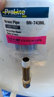
- 1/4in MIP x 2-1/2in Long Brass Pipe(BN-743NL)
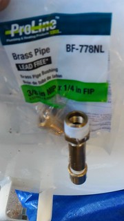
- 3/8in MIP x 1/4in FIP Brass Pipe Bushing(BF-778NL)
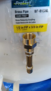
- 1/2in FIP x 3/8in FIP Brass Reducing Coupling(BF-815NL)
- CNBTR 1/2″ AC110V Multifunction Automatic Electronic Timed Air Compressed Drain Valve(not in store)
- 1/2in MIP x 1/4in FIP Brass Pipe Bushing
- 1/4in MIP x 1-1/2in Long Brass Pipe
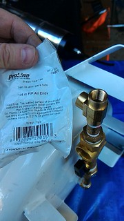
- 1/4in FIP All Ends Brass Tee(BF-703NL)
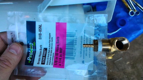
- 1/8in ID Hose Barb x 1/4in MIP – Brass(BHB-85NL)
- 2 qty 1/4in ID Hose Barb x 1/4in MIP – Brass(BHB-192NL)
- 1/4in x 1/4in x 1/4in Compression Tee – Brass(CP-12NL)
- 0.71in ID x 1/4in OD clear Vinyl Tubing x 10ft(98615)
- 1/4in ID x 3/8in OD Vinyl Tubing x 10ft
- Swagelok quick disconnect Coupler 1/4in Tubing(not in store)
- Brass 4mm ID Check Valve(not in store)
- Molex 2-Pin Connector Kit 0.093″(not in store)
- Molex 2-Pin Connector Kit 0.062″(not in store)
- 1/2in Diameter Round Strain Relief Bushing(not in store)
- Zip Tie Mounts + Ties(not in store)
- White, brown, and green 22AWG stranded wire for AC power.(not in store)
Tools Needed: (suggested)
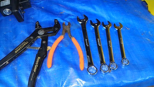
- RoboGrip type pliers (for Brass Pipe)
- Diagonal Pliers (for Vynil Tube & Zip Ties)
- A metric & SAE wrench set Author used: 11/16″, 16mm, 9/16″, and 1/2″ during his install.
- Utility Knife
- 3/8in Twist Drill Bit
- Step Drill Bit
- Molex Hand Crimping Tool
Please note: This retrofit process will likely void the warranty of your CAT air compressor especially if you perform the electrical modifications. The Author of this blog entry is not responsible for any damage you do to yourself or your property.
Duplication of or Plagiarizing from this blog entry is not permitted without written consent from the author and Pinball-Mods.com.
RetroFit the plumbing:
- Begin by determining which direction you want the drain valve to go. I’d advise you put the air compressor in its final position and determine which direction the valve assembly should go and drain. The author choose to install his valve assembly going to the right as your looking at the machine. To ease working on the compressor; put the compressor on a work surface on it’s side so you can get easy access to the drain. The Author worked up in the Z direction as he assembled the plumbing.
- Remove the stock ball valve on the underside of your air compressor’s storage tank. On my CAT; the factory installed with some clear plumber’s goop to help prevent air leaks. The result is you may have to use a little bit of force to break the clear sealant inside the threads.
- Next; install the 1/4in MIP x 1/4in FIP Brass 90 Street Elbow in the drain hole as pictured:
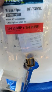
1/4in street elbow (90deg) Be sure to wrap the male end of the elbow in teflon pipe tape
- Wrap both ends of the 1/4in MIP x 2-1/2in Long Brass Pipe with pipe tape and install it into female end of the elbow. Use your robogrip or Pipe wrench to make the connection tight.
1/4in street elbow (90deg) - Wrap the male end of the 3/8in MIP x 1/4in FIP Brass Pipe Bushing with pipe tape and install it on the remaining end of the brass pipe. Snug it up with an appropriate sized wrench.
3/8in MIP x 1/4in FIP Brass Pipe Bushing - Install the 1/2in FIP x 3/8in FIP Brass Reducing Coupling onto the 1/8″ MIP fitting and tighten.
1/2in FIP x 3/8in FIP Brass Reducing Coupler - Carefully disassemble the drain valve using the top silver nut and the star washer. This should allow the black plastic body to be removed from the brass assembly. Then you have access to the brass nut holding the actuator assembly to the brass body. Remove it. Note how the device comes apart because you will need to reassemble the valve properly once its completed installed on the machine. Take care as there is a spring and small brass piece inside the brass could get lost. With the black electrical case and valve assembly removed; you’ll be able to install the brass fittings in the following steps.
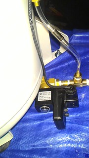
- Now thread the drain valve assembly onto the 1/2 FIP coupler from above after pipe tape-ing the male end. Make sure the final tight position of the valve is parallel with the bottom of your tank. The black switch body and actuator should have enough clearance to set just under the tank. Open the assemblies ball valve now.
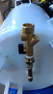
1/2in Auto Drain Value assembly - Tape the male end of a 1/2in MIP x 1/4in FIP Brass Pipe Bushing and tighten on the Valve assembly.
- Tape both ends of the 1/4in MIP x 1-1/2in Long Brass Pipe and install onto the 1/4″ FIP bushing.
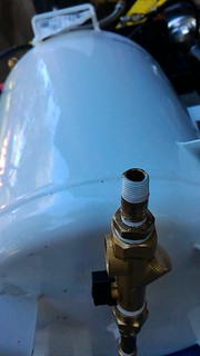
1/4in MIP x 1-1/2in Long Brass Pipe - Install the 1/4in FIP All Ends Brass Tee as shown. Ensure the final tight position has the top opening in the direction of the top of the compressor. This will be the inlet of the Problem 2 and 3 filters drains.
1/4in FIP All Ends Brass Tee - Tape the male thread of the 1/8in ID Hose Barb x 1/4in MIP and install it on the top facing opening.
1/8in ID Hose Barb x 1/4in MIP - Tape the male thread on the first 1/4in ID Hose Barb x 1/4in MIP and install it on the remaining opening of the tee. This will be the outlet for all water and will eventually go to the bucket.
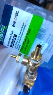
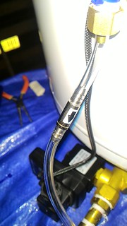
1/4in ID Hose Barb x 1/4in MIP - Thread one end of the 0.71ID vinyl tube onto the 1/8in hose barb. Cut the tube off about half way up the side of the tank.
- Slip the end of the 0.71 tube into the compression fitting and tighten it onto the bottom end of the Tee. For instructions on installing compression fittings; see this youtube video; however, note that the tee’s compression sleeve is build into the brass nut. Loosen the compression fitting from the Tee and verify the compression fitting is solid. Tape the male end of the fitting and reinstall.
- The fitting opposite the drain should be plumbed to the bottom of the Air/Water separator using additional 0.71tube. This separator will have the most volume of water; so it should have the easier path. Remove the existing black tubing on the bottom of the water seperator.
- The perpendicular fitting should be plumbed to the bottom of the Chemical Air dryer as large volumes of water are not expected from that part. Remove the existing black tubing on the bottom of the Air Dryer.
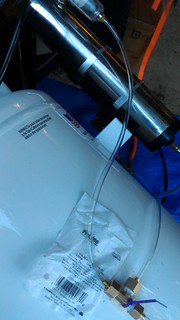
0.71in ID Hose routing - Secure the compression Tee fitting to the side of the tank using a self-adhesive tie down and a zip tie.
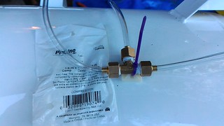
1/4in x 1/4in x 1/4in Compression Tee - Cut the 0.71ID tube between the compression tee and the 1/8″ID hose barb at about the halfway mark. This will be the location for the 4mm ID Check Valve. The direction arrow should face the hose barb so that only the water can drain and prevents at pressure air from the tank from back-flowing into the filters.
4mm Check Valve - Reassemble the solenoid valve (reverse of disassembly).

solenoid - ReAttach the electronics to the valve as shown. Note that the “AC in” port of the drain valve should be in the same direction as the 1/8in ID barb (IE facing top of compressor).
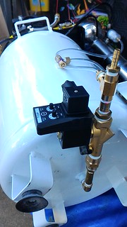
valve Electronics
The idea behind the Tee is that water drained from the filters will flow thru the check valve and pool at the outlet of the auto-drain valve. When the drain valve fires; the compressed air+water from the tank will force the pooled water after the valve up and into the bucket will provide later.
We’ll pick up the final bucket assembly after a short break of electrical wiring.
RetroFit the electrical:
Please note: The following electrical retrofit will likely void the warranty of your CAT air compressor. When in doubt consult a licensed electric professional. The Author of this blog entry is not responsible for any damage you do to yourself or your property.
The drain valve operates on 110VAC on the CAT air compressor. MAKE SURE you unplug the compressor from the wall and verify no AC power is present before proceeding. Always make sure the unit is unplugged before continuing work.
There is no clean way of getting switched AC from under the compressor’s switch cover. The Author decided to tap into the wiring harness outside the switch cover. This means that the Auto Drain valve will not always have power and the timer functionality will be effectively disabled unless you are running the compressor at a very high duty cycle. In the Authors case; he expects the auto drain valve to fire each time the compressor comes on; which should be good enough.
You could choose to wire this directly onto an AC plug so the auto drain valve fires as it is intended. This would mean you would have to unplug it each time you power off the air compressor. The Author chose to keep the wiring “inside” the compress as a single unit with one plug to supply power.
The author went overboard on this wiring job; channeling his sleeving powers to make the installation look nice, neat, and professional. He installed some “molex” style connectors as a “y” in the harness to allow the auto-drain valve to be disconnected in the future (or re-wired). This is by no means required; as you could use the same technique CAT used with crimp style connectors. The Author’s method is just one way of solving the problem.
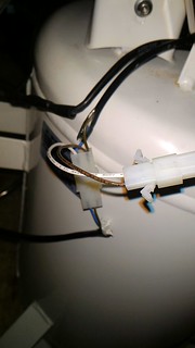
- Begin by locating the AC wiring harnesses. The Author checked under the power switch body and identified the black harness. Showing that inside the black harness there was a blue and brown wire which goes to a couple of the AC powered components on the top of the compressor. These were sealed in black heat shrink. Cut the heat shrink away to reveal CAT’s crimped pin connectors.
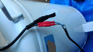
remove heatshrink - Cut away the existing crimped-on connectors and use a 0.093 2pin connectors with a Y connection (white/brown) in the picture. Basically we’re adding another connection the compressor side of the harness. Crimp the 0.093 male connector for the compressor side and the female connector on the accessory side. The Author used female sockets on the male connector and male pins on the female connector. The idea here is that the pins when disconnected from the main harness cannot easily be touched – lessening the shock possibility.
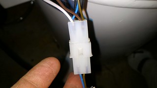
0.093 AC connector - Crimp on the 0.062″ connector for the new auto-drain valve. Again male connector, female sockets compressor side. Female connector, male pins on the drain valve side.
0.062 AC connector - Route the drain valve ac connection over the top of the compressor, down near the Tee. Disconnect the AC inlet on the drain valve and wire the socket. The author connected the white hot wire to pin 1, the brown neutral to pin2, and the green ground to pin3.

valve electical connection - But… wait Seymour. A 3rd Ground connection? I’m lost… Clearly the AC wiring harnesses of the compressor only have a hot and neutral connection. There’s no third wire. The Author got the ground connection from a screw at the top of the compressor. If you look under the power switch; you’ll see that the ground basically ties into the metal tank. My multimeter check show that any threaded connection will serve as a good ground. More data to follow.
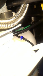
- With the drain wired; put a 1/2in strain relief in the hole and route the ac cable up to the same mount used for the Tee and secure it there.
strain relief - Route the drain power behind the handle and secure it with another mount and zip tie.
secure AC - Finally, secure the new connectors onto the other side of the compressor tank. The Author didn’t have large enough heatshrink for the 0.093″ connector; but, he secured it the 0.062″ connector with heatshrink and a zip-tie mount.
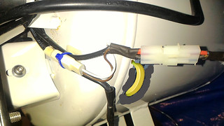
secure AC harness
With the electrical complete; you can test the functionality of the auto drain valve. When you first turn on the compressor; the auto valve will fire releasing air out the 1/4in barb fitting. Note your tank will probably be empty when you first fire it up. For that you can watch that the LED comes on Green then goes to red when the valve is closed. You can also let the compressor run for a minute or so and then turn off the compressor with some air in the tank. Then turn it back on and you should hear the drain valve open.
Because the author has his valve fire each time the compressor turns on; he set the time open to the shortest value. This should keep the tank empty of water each time the compressor turns on.
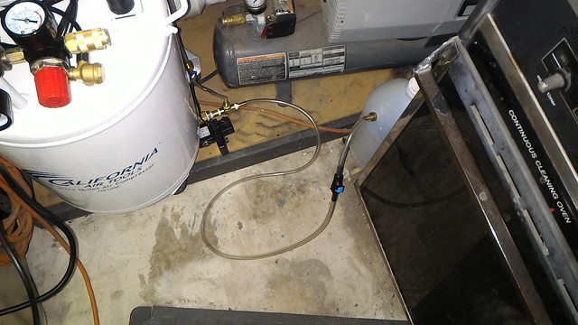
RetroFit Plumbing (continued):
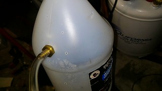
With the electrical complete and tested; it’s time to plumb the exit barb into a reservoir of some type. For this it’s really up to you as to what container you want holding the water. The Author had just used up the last of his Windshield additive so this made a simple, cost effective reservoir. You can use anything you’d like; but we’d recommend something sealed (with a lid) to limit accidental spilling and blow back from the compressed air+water.
- On this reservoir; we cut 3 ‘v’shaped holes in the top of the jug above our intended inlet. This is to allow the air to escape but try and contain the water. Failure to put vent holes will likely lead to catastrophic failure of your container. 😀
- Identify an inlet location which will be the final 1/4in ID Hose Barb x 1/4in MIP. Wanted the water under pressure to eject downward; so drilled on the top angled surface of the jug. Using a 3/8″ drill bit; drilled the pilot hole and the used the step drill to get right sized hole so the barb could be threaded.
reservoir inlet - Connect a section of 1/4in ID vinyl tubing to the reservoir.
- After about 4-6 inches of tubing; cut. Install the swagelok quick disconnect. On this part; connect the button side which auto closes to the reservoir side. This way; the reservoir remains pseudo-sealed until while you transport it to your dumping location.
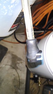
Quick Disconnect Coupler - Connect the other end of the coupler to 1/4in ID tubing.
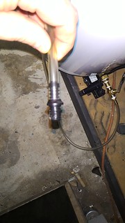
Quick Disconnect Coupler (male) - Finally cut a suitable length of the tubing and connect it to the exposed 1/4in barb on the bottom of your tank.
Final Connection: 1/4″ barb
I have yet to use this system extensively; but I’ll report back if there are any issue and their possible solutions. Hopefully, you have found this blog post useful. If so; feel free to comment below or share on social media.
Enjoy!