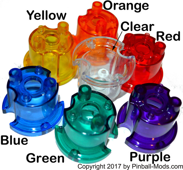
A little over a year ago; we began distributing Transparent / Translucent Pop Bumper Bodies manufactured out of Germany by Pinball.Center. We announce back then that we were the exclusive distributor for the North American American Market. These transparent pop bumper bodies are available in 9 modder friendly colors and should fit most modern Pinball machines:
Bally from 1988+
Williams from 1976+
Stern (including modern)
Data East
Sega
These pop bumper bodies were imported from Pinball.Center and will ship from Austin, TX to any North American address.
Lately many people have been asking me when we’ll restock Clear Bodies instead of the frosted Clear we now offer. This is best summed up by this response:
I can’t commit at all on the Clear Pop Bodies; here’s the reason:
I was running low; so I ordered some more Williams Clear Drops, some GID Star posts, and 150 Clear bodies from Pinball.Center so I wouldn’t run out.
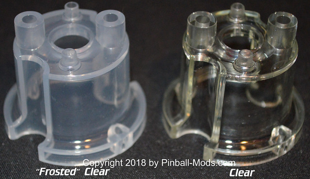
The Clear Bodies arrived in the frosted appearance:
Pinball.Center basically said I could return them; but they had no idea when (or if) they could fix their vendor to get them in Clear. I wanted to be upfront and honest with their appearance and didn’t want to leave no options for those people so I added the new color and put the Clear Out-Of-Stock. If you look at Pinball.Center’s original product photo – you’ll see that they pretty much consider the two equivalent. http://www.pinball.center/en/shop/pinball-parts/playfield-parts/bumper-parts/2420/pop-bumper-body-transparent-03-7443-5
As a result; I’m not sure I’ll ever be able to get true Clear again.
When I’m ready to reorder (maybe in Feb 2019); I’ll ask again – but I wouldn’t hold my breath for future stock.
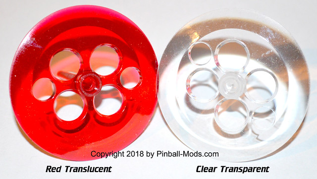
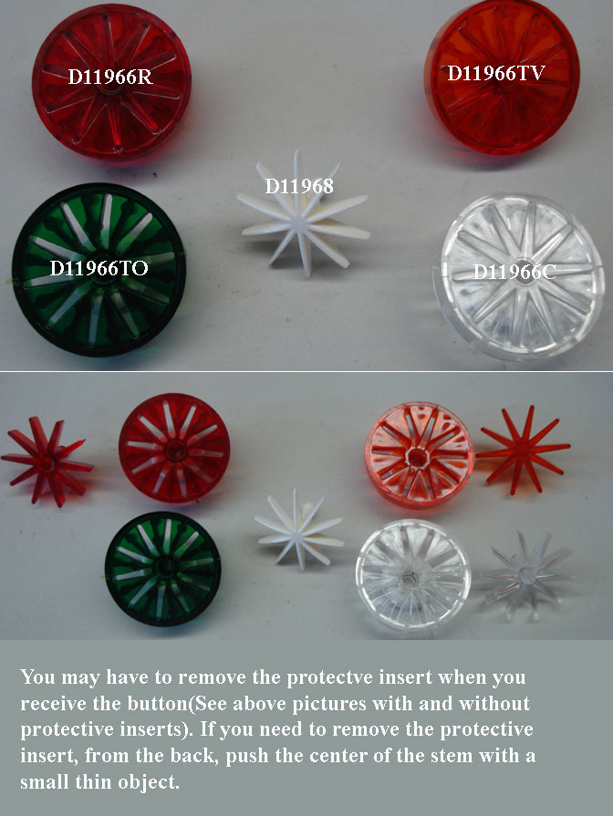
About 8 months later; I announced the immediate availability of translucent pop bumper skirts. At this time they were only available in translucent Red and transparent Clear:
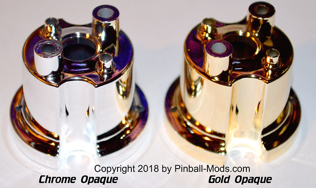
Finally, to round out our Pop bumper products; we announced our own version of the Pop Bumper Thingys available in both silver and gold glitter. Both products are laser cut here in our facility in Austin, TX and gold is an exclusive color available only from our webshop. Because these are laser cut here; we can customize the design with any color acrylic available. If this interests you; please contact us.
During Amazon Prime day; I decided to enhance the security of my driveway and Garage by adding a Foscam Outdoor PTZ (FI9928P) HD 1080p IP Camera. While I had WIFI in the garage; I wanted to wire this camera in with the other camera watching the front door but I wanted to position this camera on the Left side of the driveway so it could watch the garage door as well as keep an eye on the driveway. To do this meant I was going to need to run a very long power cable along with a 16-20foot CAT5E cable but I decided I’d rather run a Power-Over-Ethernet (PoE) connection to eliminate the long power cable run and run a single CAT5 POE configuration. The Foscam FI9928P does not natively support POE; so I’d have an injector and a splitter to enable POE for this camera.
This Blog entry is a expansion of my Amazon Review of the WT-GPOE-1-AB by PoE Texas. This device is a passive splitter / Injector which can be used on both ends of a PoE connection to inject and breakout the DC connections. I wanted to add a little detail here incase someone needs to replicate my work on their personal installation. This should be applicable to anyone trying to use PoE for any network device which has a power brick.
Installation is pretty simple. All you are going to need is two of the WT-GPOE-1-AB which thankfully comes with some DC splitter cables to connect them up to a DC power brick, some Cat5E cables, and maybe a few screws to mount the WT-GPOE-1-ABs to the wall. Total cost would probably be under $20 if you have the cat5 cables on hand. The Author picked the WT-GPOE-1-AB for several reasons:
Support Gigabit Ethernet speeds
Allows for use any voltage on PoE up-to-56V for a total of 60watts. In our case the Foscam Power adapter is capable of delivering 12VDC at 2amps for a total of 24watts.
Can be used on both ends of the PoE link.
Carries DC across all 4 pairs of the Ethernet link maximizing current carrying capabilities of the CAT6 Cable.
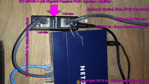
Let’s start with the Network side of the PoE connection. To do this you are going to want to connect the WT-GPOE-1-AB to the network switch as pictured:
Network Side of POE
The LAN side of the WT-GPOE-1-AB connect to the network switch or to anything on “lan” side of your device which you’d normally plug the IP camera into. The PoE connection would become the side which carries both LAN data and the DC power from the power supply. Finally; you’d connect the camera’s power supply directly to 45+78- DC jack of the WT-GPOE-1-AB.
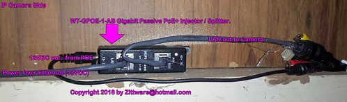
Camera Side of POE
On the Camera side of the POE cable; you need to split the Power from the Ethernet (data) using another WT-GPOE-1-AB… although the configuration isn’t quite as obvious for some reason. The PoE cable from above; plugs into the “LAN” connector and the Camera plugs into the DC jack at 12-34+. The Camera’s data port then connects to the remaining “POE” RJ45 jack. The Camera power is connected with a DC to DC barrel connector also available on Amazaon.
Using two WT-GPOE-1-AB‘s I was able to transmit the DC power for the camera approximately 20ft along with the gigabit data for the camera. The small physical form factor of the WT-GPOE-1-AB allows it to fit easily on top of my garage door ledge and not interfere with the opening or closing of the garage door.
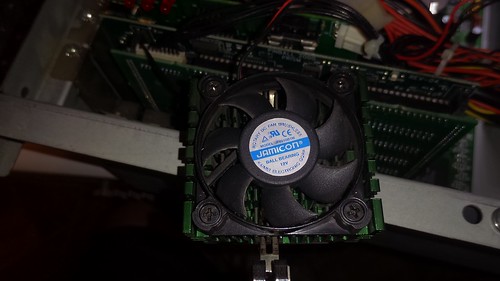
When I first got my Revenge From Mars from a local Pinhead; the fan was clogged with dust and grime. At the time; I simply cleaned the fan, removed the sticker, and added some oil to the bearings. This lasted about 3months before the fan began to make some horrible noises because the bearings were shot. I “lived with it”; but it remained on my todo list.
For years; I had watched threads about Pin2k in Pinside… always feeling a little guilty I had not eliminated the risk that my CPU fan would die… overheat the cpu… and put my RFM in jeopardy of force converting to NuCore or Pinbox. Today was the day I vowed to resolve that noisy fan.
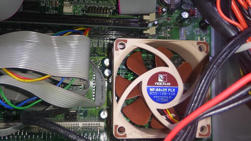
First; I did not want to buy NOS (new old stock) of some 50mm fan made back in 2000 or some china knockoff that wouldn’t last another 18 years. I wanted a high quality fan with very little noise; but a good performer. I’ve grown to like the Noctura brand of fans because they aren’t cookie cut china knock offs. Noctura does not sell a drop-in-replacement for 50mm fans. Going smaller usually means less air flow with a higher “whine” because the fan blades have to go much faster to move more air. So I decided that I was going to try and use the NF-A6x25 FLX 60mm fan:
and build an adapter to fit the larger fan over the existing heatsink. This blog entry documents my solution, provides a TAPR/NCLed DXF for my adapter, and links to a Shapeways implementation of my adapter my fellow pinball enthusiasts to use.
First, I removed the CPU box from my RFM and pulled out the existing CPU heatsink: Stock Pin2k CPU Fan/Heatsink
Once I had the CPU heatsink free; I unscrewed the old FAN from the heatsink. This was done for two reasons;
I need the heatsink to take caliper measurements in order design a 60mm to 50mm bracket.
Eventually; I’d toss the worthless 50mm fan – but wanted to keep it incase I couldn’t find a working solution.
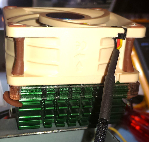
Obviously; the 60mm fan wouldn’t fit within the 50mm cavity of the heatsink; so I knew I wanted to use some 1/4inch clear Acrylic as an “adapter”. I went into qCAD resulting in a DXF file which I could then send to my laser cutter. I wanted to reuse the 50mm fan/heatsink screws and the 4 qty Vibration-Compensators provided in the Noctura kit. My second proto resulted in success and looked like this: 60 to 50mm Fan Adapter
Reusing the 4 qty 50mm countersunk heatsink screws; I attached the clear acrylic bracket to the top of the heatsink. Then I put the 4 qty Vibration-Compensators provided in the Noctura kit thru the acrylic bracket and into the NF-A6x25 fan. The whole assembly fit together quiet nicely. 60mm Fan Adapter – Test Fit
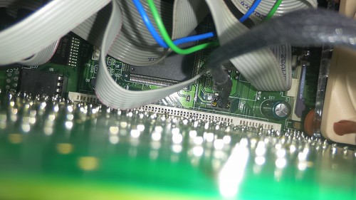
I carefully; reinstalled the fan-sink combo back onto the cpu and socket. This was a little tricky because the 60mm fan is bigger; but as you can see the whole contraption fits well: 60mm Fan Adapter – Motherboard Install
Conveniently; my Pinball 2000 motherboard had a FAN header right next to the cpu socket; so I simply attached the CPU fan’s 3pin PWM connector to that unused mobo connection: 60mm Fan Adapter – Fan Header
I powered up the Pin2k system on my bench with both the original and the new fan connected. !That old fan really needed to be replaced! This new fan is ultra quiet; I don’t think you can hear the fan over the PSU fan even when the box is open. You won’t be able to hear the fan at all when its in the backbox behind the backglass. Success!
For years I’ve been limping along with a very noise older model Air compressor for my Modding needs. Recently; I upgraded from a Universal Laser 25E laser to an Epilog Legend 24TT laser cutter. The former could be outfitted with Air Assist; while the latter came pre-plumbed for Air assist. The issue is that the Air Assist works best if the lens doesn’t get splash back form the Air assist when it contains water.
Air compressors work by compressing the gas of surrounding air which contains water vapor. This water vapor leaves the compressor very hot along with the compressed air stream. As it sits under pressure; the water vapor condenses as it cools leaving water in the air lines. A properly configured Air Assist needs to remove that water vapor so it cannot exit the assist nozzle and insta-cool a warm laser lens. This leads to cracked or otherwise damaged lenses which can be expensive or lead to downtime as a new lens is sought.
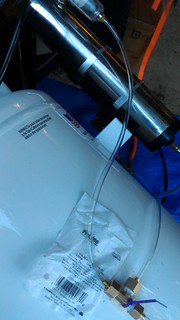
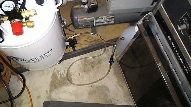
This air compressor was purchased straight from California Air Tools with less than 50hrs at a fair discount and automatically cools the air stream as it exits the Tank by running thru a radiator on top of the tank. This radiator is cooled by some fans to keep the radiator near room temperature causing the water vapor to condense out of the compressed air. The air then passed thru an air/water seperator. This separator causes a significant amount of water to be deposited in it’s reservoir where a tube just drips the water onto the ground (problem #2).
The Air stream is then plumbed to a Activated Alumina desiccant Air Dryer where additional drying is done by chemical reaction. The bottom of this air dryer is also plumbed with a tube which just drips onto the ground (problem #3). The main problem (problem #1); however, that the tank itself needs to be drained periodically as is required for ALL Compressors to prevent the air tank from rusting inside. If I had been purchasing new; I may have just purchased a 10010DACD which as a Automatic Drain Valve installed at the factory… but since this was a discounted unit; I couldn’t get drain valve option. Additionally; the factory charges an additional $150 to cover the installation and plumbing for the Auto-valve; I do not know if CAT will rectify the tubing outputs of the separator and dryer, so this may be an interest read for owners of the more expensive unit.
The result is I need to plumb my own automatic drain valve while making an attempt to tidy up the separator and air drier water outlets so they all exit the machine into a reservoir which can be dumped periodically instead of spraying the water all over my garage floor. This Blog entry is the documentation of what I did in the hopes it can help some other budding laser hobbyists in creating their own Air Assist setup.
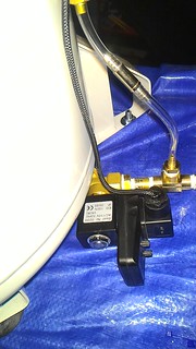
I started by researching the concepts behind CAT’s Automatic Drain valve which is pictured here:
As best as I can figure is this is no different from any of the other auto-drain valves available for less than $30 on Amazon. It’s probably even made in China.
I started by researching auto-drain values on youtube where I came across Farmboy’s Garage’s implementation. While complete; it’s kind of scary how he just lets the valve blow water in the the corner of his garage. As he states in a later video; it scares him every time it triggers. My goal is to try to keep all of the water draining into a lidded bucket so the water can be contained and easily dumped as my garage doesn’t have any drains and the compressor is near the interior wall rather than the external garage door.
To plumb the cheaper auto-drain valve; I’m going to need to purchase some piping accessories and some vinyl tubing. I came up with this crude napkin sketch before I went to Lowes to “engineer” a solution in their plumbing section. Here’s a shopping list from Amazon if you’d rather purchase as much as you can using your Prime Membership. While this blog entry will focus on adding a auto-drain valve to my compressor; it will probably be very similar to your air compressor. Feel free to reuse as much of this design as you’d like. IF you decide to purchase from your local Lowes; I’ve included pictures of the bags for each step and included the bag part numbers in the shopping list below between ()s.
The total cost of this shopping list isn’t exactly known as the Author has some parts on hand. The plumbing and Auto-Drain valve combined costs about $80 in total. YMMV as costs on these items can vary. Time wise; again it’s tough to say because I had it spread over several days as I waited for parts to arrive from Amazon prime. I estimate you could finish the whole project in an afternoon if you have everything ready to go.
Please note: This retrofit process will likely void the warranty of your CAT air compressor especially if you perform the electrical modifications. The Author of this blog entry is not responsible for any damage you do to yourself or your property.
Duplication of or Plagiarizing from this blog entry is not permitted without written consent from the author and Pinball-Mods.com.
RetroFit the plumbing:
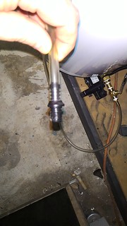
Begin by determining which direction you want the drain valve to go. I’d advise you put the air compressor in its final position and determine which direction the valve assembly should go and drain. The author choose to install his valve assembly going to the right as your looking at the machine. To ease working on the compressor; put the compressor on a work surface on it’s side so you can get easy access to the drain. The Author worked up in the Z direction as he assembled the plumbing.
Remove the stock ball valve on the underside of your air compressor’s storage tank. On my CAT; the factory installed with some clear plumber’s goop to help prevent air leaks. The result is you may have to use a little bit of force to break the clear sealant inside the threads.
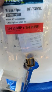
Next; install the 1/4in MIP x 1/4in FIP Brass 90 Street Elbow in the drain hole as pictured:
1/4in street elbow (90deg)
Be sure to wrap the male end of the elbow in teflon pipe tape
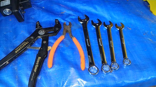
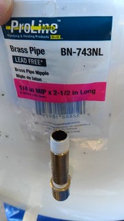
Wrap both ends of the 1/4in MIP x 2-1/2in Long Brass Pipe with pipe tape and install it into female end of the elbow. Use your robogrip or Pipe wrench to make the connection tight.
1/4in street elbow (90deg)
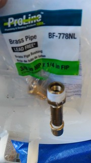
Wrap the male end of the 3/8in MIP x 1/4in FIP Brass Pipe Bushing with pipe tape and install it on the remaining end of the brass pipe. Snug it up with an appropriate sized wrench.
3/8in MIP x 1/4in FIP Brass Pipe Bushing
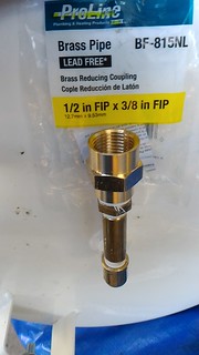
Install the 1/2in FIP x 3/8in FIP Brass Reducing Coupling onto the 1/8″ MIP fitting and tighten.
1/2in FIP x 3/8in FIP Brass Reducing Coupler
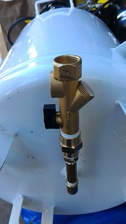
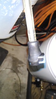
Carefully disassemble the drain valve using the top silver nut and the star washer. This should allow the black plastic body to be removed from the brass assembly. Then you have access to the brass nut holding the actuator assembly to the brass body. Remove it. Note how the device comes apart because you will need to reassemble the valve properly once its completed installed on the machine. Take care as there is a spring and small brass piece inside the brass could get lost. With the black electrical case and valve assembly removed; you’ll be able to install the brass fittings in the following steps.
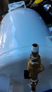
Now thread the drain valve assembly onto the 1/2 FIP coupler from above after pipe tape-ing the male end. Make sure the final tight position of the valve is parallel with the bottom of your tank. The black switch body and actuator should have enough clearance to set just under the tank. Open the assemblies ball valve now.
1/2in Auto Drain Value assembly
Tape the male end of a 1/2in MIP x 1/4in FIP Brass Pipe Bushing and tighten on the Valve assembly.
Tape both ends of the 1/4in MIP x 1-1/2in Long Brass Pipe and install onto the 1/4″ FIP bushing.
1/4in MIP x 1-1/2in Long Brass Pipe
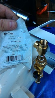
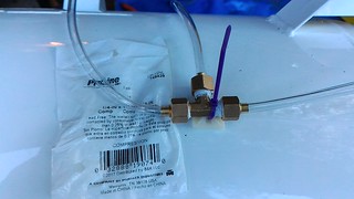
Install the 1/4in FIP All Ends Brass Tee as shown. Ensure the final tight position has the top opening in the direction of the top of the compressor. This will be the inlet of the Problem 2 and 3 filters drains.
1/4in FIP All Ends Brass Tee
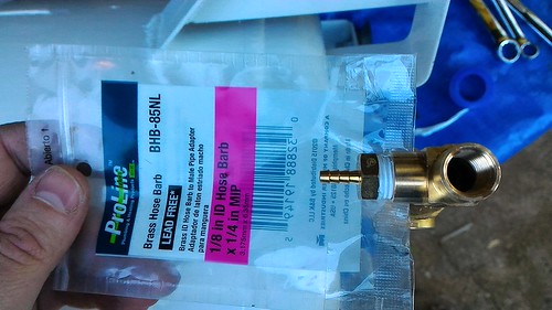
Tape the male thread of the 1/8in ID Hose Barb x 1/4in MIP and install it on the top facing opening.
1/8in ID Hose Barb x 1/4in MIP
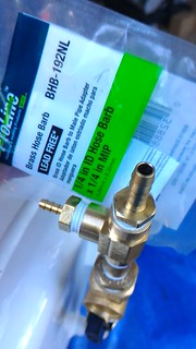
Tape the male thread on the first 1/4in ID Hose Barb x 1/4in MIP and install it on the remaining opening of the tee. This will be the outlet for all water and will eventually go to the bucket.
1/4in ID Hose Barb x 1/4in MIP
Thread one end of the 0.71ID vinyl tube onto the 1/8in hose barb. Cut the tube off about half way up the side of the tank.
Slip the end of the 0.71 tube into the compression fitting and tighten it onto the bottom end of the Tee. For instructions on installing compression fittings; see this youtube video; however, note that the tee’s compression sleeve is build into the brass nut. Loosen the compression fitting from the Tee and verify the compression fitting is solid. Tape the male end of the fitting and reinstall.
The fitting opposite the drain should be plumbed to the bottom of the Air/Water separator using additional 0.71tube. This separator will have the most volume of water; so it should have the easier path. Remove the existing black tubing on the bottom of the water seperator.
The perpendicular fitting should be plumbed to the bottom of the Chemical Air dryer as large volumes of water are not expected from that part. Remove the existing black tubing on the bottom of the Air Dryer.
0.71in ID Hose routing
Secure the compression Tee fitting to the side of the tank using a self-adhesive tie down and a zip tie.
1/4in x 1/4in x 1/4in Compression Tee
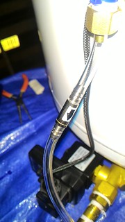
Cut the 0.71ID tube between the compression tee and the 1/8″ID hose barb at about the halfway mark. This will be the location for the 4mm ID Check Valve. The direction arrow should face the hose barb so that only the water can drain and prevents at pressure air from the tank from back-flowing into the filters.
4mm Check Valve
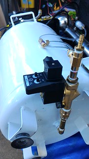
Reassemble the solenoid valve (reverse of disassembly).
solenoid
ReAttach the electronics to the valve as shown. Note that the “AC in” port of the drain valve should be in the same direction as the 1/8in ID barb (IE facing top of compressor).
valve Electronics
The idea behind the Tee is that water drained from the filters will flow thru the check valve and pool at the outlet of the auto-drain valve. When the drain valve fires; the compressed air+water from the tank will force the pooled water after the valve up and into the bucket will provide later.
We’ll pick up the final bucket assembly after a short break of electrical wiring.
RetroFit the electrical:
Please note: The following electrical retrofit will likely void the warranty of your CAT air compressor. When in doubt consult a licensed electric professional. The Author of this blog entry is not responsible for any damage you do to yourself or your property.
The drain valve operates on 110VAC on the CAT air compressor. MAKE SURE you unplug the compressor from the wall and verify no AC power is present before proceeding. Always make sure the unit is unplugged before continuing work.
There is no clean way of getting switched AC from under the compressor’s switch cover. The Author decided to tap into the wiring harness outside the switch cover. This means that the Auto Drain valve will not always have power and the timer functionality will be effectively disabled unless you are running the compressor at a very high duty cycle. In the Authors case; he expects the auto drain valve to fire each time the compressor comes on; which should be good enough.
You could choose to wire this directly onto an AC plug so the auto drain valve fires as it is intended. This would mean you would have to unplug it each time you power off the air compressor. The Author chose to keep the wiring “inside” the compress as a single unit with one plug to supply power.
The author went overboard on this wiring job; channeling his sleeving powers to make the installation look nice, neat, and professional. He installed some “molex” style connectors as a “y” in the harness to allow the auto-drain valve to be disconnected in the future (or re-wired). This is by no means required; as you could use the same technique CAT used with crimp style connectors. The Author’s method is just one way of solving the problem.
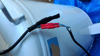
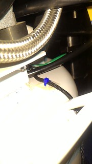
Begin by locating the AC wiring harnesses. The Author checked under the power switch body and identified the black harness. Showing that inside the black harness there was a blue and brown wire which goes to a couple of the AC powered components on the top of the compressor. These were sealed in black heat shrink. Cut the heat shrink away to reveal CAT’s crimped pin connectors.
remove heatshrink
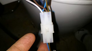
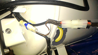
Cut away the existing crimped-on connectors and use a 0.093 2pin connectors with a Y connection (white/brown) in the picture. Basically we’re adding another connection the compressor side of the harness. Crimp the 0.093 male connector for the compressor side and the female connector on the accessory side. The Author used female sockets on the male connector and male pins on the female connector. The idea here is that the pins when disconnected from the main harness cannot easily be touched – lessening the shock possibility.
0.093 AC connector
Crimp on the 0.062″ connector for the new auto-drain valve. Again male connector, female sockets compressor side. Female connector, male pins on the drain valve side.
0.062 AC connector
Route the drain valve ac connection over the top of the compressor, down near the Tee. Disconnect the AC inlet on the drain valve and wire the socket. The author connected the white hot wire to pin 1, the brown neutral to pin2, and the green ground to pin3.
valve electical connection
But… wait Seymour. A 3rd Ground connection? I’m lost… Clearly the AC wiring harnesses of the compressor only have a hot and neutral connection. There’s no third wire. The Author got the ground connection from a screw at the top of the compressor. If you look under the power switch; you’ll see that the ground basically ties into the metal tank. My multimeter check show that any threaded connection will serve as a good ground. More data to follow.
With the drain wired; put a 1/2in strain relief in the hole and route the ac cable up to the same mount used for the Tee and secure it there.
strain relief
Route the drain power behind the handle and secure it with another mount and zip tie.
secure AC
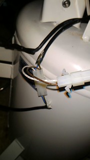
Finally, secure the new connectors onto the other side of the compressor tank. The Author didn’t have large enough heatshrink for the 0.093″ connector; but, he secured it the 0.062″ connector with heatshrink and a zip-tie mount.
secure AC harness
With the electrical complete; you can test the functionality of the auto drain valve. When you first turn on the compressor; the auto valve will fire releasing air out the 1/4in barb fitting. Note your tank will probably be empty when you first fire it up. For that you can watch that the LED comes on Green then goes to red when the valve is closed. You can also let the compressor run for a minute or so and then turn off the compressor with some air in the tank. Then turn it back on and you should hear the drain valve open.
Because the author has his valve fire each time the compressor turns on; he set the time open to the shortest value. This should keep the tank empty of water each time the compressor turns on.
RetroFit Plumbing (continued):
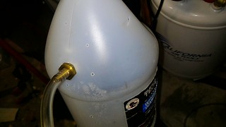
With the electrical complete and tested; it’s time to plumb the exit barb into a reservoir of some type. For this it’s really up to you as to what container you want holding the water. The Author had just used up the last of his Windshield additive so this made a simple, cost effective reservoir. You can use anything you’d like; but we’d recommend something sealed (with a lid) to limit accidental spilling and blow back from the compressed air+water.
On this reservoir; we cut 3 ‘v’shaped holes in the top of the jug above our intended inlet. This is to allow the air to escape but try and contain the water. Failure to put vent holes will likely lead to catastrophic failure of your container. 😀
Identify an inlet location which will be the final 1/4in ID Hose Barb x 1/4in MIP. Wanted the water under pressure to eject downward; so drilled on the top angled surface of the jug. Using a 3/8″ drill bit; drilled the pilot hole and the used the step drill to get right sized hole so the barb could be threaded.
reservoir inlet
Connect a section of 1/4in ID vinyl tubing to the reservoir.
After about 4-6 inches of tubing; cut. Install the swagelok quick disconnect. On this part; connect the button side which auto closes to the reservoir side. This way; the reservoir remains pseudo-sealed until while you transport it to your dumping location.
Quick Disconnect Coupler
Connect the other end of the coupler to 1/4in ID tubing.
Quick Disconnect Coupler (male)
Finally cut a suitable length of the tubing and connect it to the exposed 1/4in barb on the bottom of your tank.
Final Connection: 1/4″ barb
I have yet to use this system extensively; but I’ll report back if there are any issue and their possible solutions. Hopefully, you have found this blog post useful. If so; feel free to comment below or share on social media.
This is the kind of scope I fell in love with at work; but is much older, thereby within my budget. This scope is unique in that it instruments using Windows XP as the host operating system and has a full Pentium(r) III cpu with a whopping 512MB of main DRAM. The scope is really overkill for me – as I don’t see the need for 1GHz capability; but the 4 channel option is good as will be the +16 logic capability. The post below is a series of notes I took to upgrade this machine – documented for others on the internet.
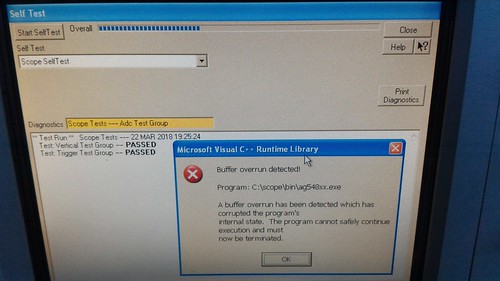
First; The scope had some issues when it first arrived. The Acquisition boards failed self test (more specifically, the application just died with buffer overrun and exits).
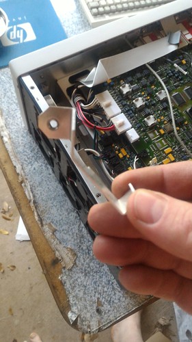
All channels reported random noise. The seller had tested the scope before he shipped; so the damage occurred during shipping. The Seller offered to exchange the scope but I convinced him that I should open the cover to see if any cables were loose (and/or reseat them). He agreed once we had a quick phone conversation. Armed with the Service manual I set about disassembling my new scope.
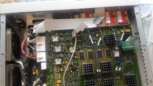
Upon opening the top cover; I saw nothing out of place, other than a extra screw being loose in the scope. From the service manual; I knew the ADC board was mounted under the motherboard behind the bottom cover so I removed it. Once I remove it I saw something very suspect:
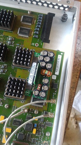
Um… yeah; that ain’t right. At first I thought that bracket was suppose to hold the cables in place… but Then I noticed the VRM was also loose:
Yeap; that’ll do it… The ADC board was getting no power; so it was reporting random noise. I re-installed the VRM in it’s black socket and the screwed the bracket to it screw hole next to using the loose screw I found. I was a little concerned the bracket, screw, and VRM loose in the machine while I was attempting to get it to work would have caused irreparable damage – but I’d gone this far… so, I powered up the scope; saw waveforms… and it passed Self-Test. 😉
With the scope now functional; I needed to turn my attention to the OS installed on the beast. It had WinXP SP2 installed which is long out of date. Infact, Microsoft EOLed WinXP and no longer supports it as of April 2014. To make matters worse; it had an HP corporate OS build on it. It was set to an internal proxy server I didn’t have access to. So; I need to get a clean SP3 install on it. I spend about 4 days on this struggling by using an old XP RTM CD I had… then I tried a slipstreams SP3 image… all were giving me Key (licensing) issues. I didn’t have any recovery CDs from Agilent in my accessories bag. Before I got too far down the XP install hole – and while I had the Scope still open from the repair above; I decided to make a backup of the 4200rpm 20GB IDE mobile drive it had in it. Using CloneZilla I made a backup copy and then “restored” it to a VMWare Virtual Machine I had running on my main development PC. While tinkering around in the backed up virtual machine I noted that there was a “recovery partition” as /dev/sda4. In a hail mary; I set the recovery partition to active and unhidden and booted the drive in the scope. I was greeted with a Agilent notice that continuing would restore my scope to factory defaults! I let it restore the WindowsXP image and rebooted. But then had to go back into gparted and set sda4 to hidden and sda3(winxp) to active and boot. Windows XP SP1 came online with no bloat. It was pre-activated (due to Agilent’s OEM keys in the bios).
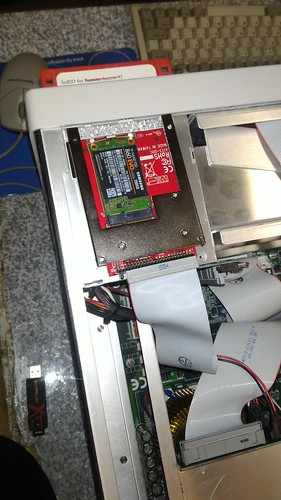
I wasn’t real happy with the 4200rpm laptop drive. It’s slow, old, and well – just sad in these modern days of SSDs plus SSDs in a Scope for reliability makes more sense to me. Why not just use a PATA SSD? Well; I’m not real fond of the “no name” brands available via Amazon these days. I had a lot of success using an mSATA Intel SSD w/ with a IDE to mSATA adapter for my NAS’s read cache… so thought I’d try my luck with this configuration. I ordered a Samsung Evo 860 250GB mSATA drive and a 44pin mobile IDE adapter to mSATA using Amazon Prime.
I restored my backed up copy of the hard drive to the mSATA drive; and then restored the factory image to the SSD and temporarily placed it on top of the scope while I was testing to ensure it all worked.
This also allowed me to move the drive to my VM where I could easily set active partitions and eventually use GParted to move sda4(RECOVERY) to the end of the drive and expand sda3 to a maximum size (~230GB). I had some concerns; but WinXP and the Motorola VP22 motherboard had no complaints about an order of magnitude larger partition.
With the SSD good; the saga of trying to get Windows XP up to SP3 with all security patches installed began. This was a lot harder than it should have been. I don’t know what the deal was… but I’m sure it has to due with the fact that XP has been “dead” for almost 4 years. No security updates, ect. I finally ended up downloading WinXP SP3 “offline” patch, IE7 & IE8 “offline” updates, and finally a cumulative IE8 security rollup. With this I upgraded WinXP SP1 -> SP3, rebooted. IE7, rebooted. IE8, rebooted, IE8 cumulative rollup, rebooted. Windows Update still wouldn’t prompt me for a whole slew of patches, so I was using some Google FU to follow some advice of some random people on the internet and booted into Safe Mode. When I did that; WindowXP safe mode did some additional installations that regular mode wouldn’t. I rebooted back into normal mode and still didn’t get any notifications of updates. My issue is that something was happening in the background as wuauclt was taking 100% of my CPU… but it never seemed to do anything useful. I was about to give up; so I set Windows Update service to “Manual” in services.msc and then went back to google.
My last effort was to set Windows Update to only notify me of updates; but not download and let me choose, then issued the command to kick off an update: wuauclt /resetauthorization /detectnow
This caused Windows to almost immediately put the familiar yellow shield in my taskbar telling me there were a large number of updates. Yeah! I then rebooted and got a welcome message:
Several reboots later; I had every single one of the WinXP patches available.
Now; Microsoft is still supporting Windows XP… but only for Point of Sale systems. Someone smarter than me reported this clever registry hack to get these security patches thru April 2019.
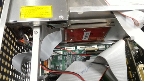
With Security patches installed; I could safely install the drive in the scope using the original mounting bracket:
and installed it in the machine:
Why did I go thru all of this? Well; the CPU in these systems is from March 2000. The RAM is small by today’s standards. Additionally; a friend of mine at work told me that Agilent (Keysight) likes to charge for OS upgrades. I couldn’t find any evidence of this – but I knew that I’d want Win7 on the box… and Win7 would not like the single thread, single core, Pentium III running at 1GHz. It also wouldn’t like the small memory. I had serious doubts that the scope software would even function well with a heavier OS. So; I needed to leave the scope in WinXP but put as many security patches on the system to help protect it from my home network.
Sadly; I can’t seem to find a Windows XP compatible Antivirus protector to run on the box. Looks like everyone has implemented changes to their software to only support Win7 and beyond. I guess what I’ll need to do is revisit later or just make sure I have a backup copy of the drive if anything happens.
My last change hasn’t yet been implemented – but will be shortly. I need USB3.0 on this machine. USB1.1 is painfully slow when trying to load the OS. My plan is to pull the GPIB card from the machine (not needed for my application) and install a PCI USB3 card which claims to be WinXP. I’ll report back later if successful.
Additionally; I plan to rack mount this scope above my electronic workbench as it’s really too big for it. More on that later.
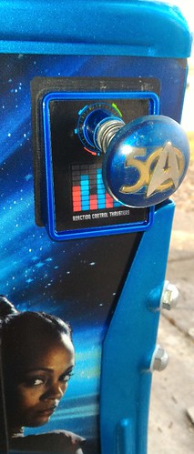
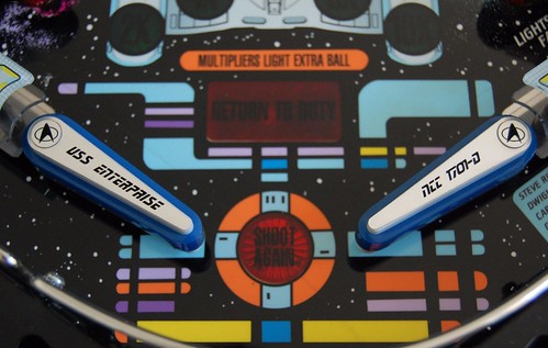
A customer of mine graciously agreed to sell me his Shooter housing decal from aurich‘s Alternate decal set; as a result, I was able to finally finish my custom shooter housing and knob.
custom 50th Anniversary Shooter Knob – Stern Star Trek
I had a shooter housing custom powder coated LE blue and installed the Decal. The knob is 3D printed at Shapeways from my custom design:
in polished Nickel and I powder coated it LE blue to match the housing.
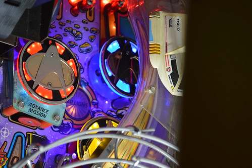
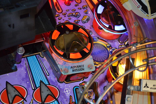
The Data East Chase rope lights used in two Data East Pinball machines (Star Trek: 25th) and Hook) are a huge problem on the game. So much so; that my Ebay-purchased game came with no rope lights at all. 🙁 This blog series walks thru my intention of recreating the chase rope lights – but made out of LEDs so they use less current, generate less heat, and can be used for decades without any issues.
First, some credit – Patofnaud on Pinside wrote a great tutorial on repairing these chase lights. I used this pinside thread almost exclusively for this blog series and if you happen to have the original rope lights; please take a look at his tutorial.
My game has no chase lights to repair; so I’m going to have to replicate the chase lights. I decided that I didn’t want to try and re-configure a standard off the shelf rope light because they likely don’t support doing a +12VDC common with three ground leads as discussed in Patofnaud’s post #1. Additionally; I don’t have exact specs of the rope light w/ regards to light spacing, diameter of the rope, ect. Since I’m going to have to recreate the lamps; I have decided to do a conversion to LEDs… specifically, using some “fairy light LEDs” which have recently become available on the market. I started by going to Hobby Lobby and buying a set of their battery operated lights using a 40% off coupon. Amazon has a whole bunch of alternate versions of this product… so you might be better off looking at Amazon if you don’t have a Hobby Lobby near you. B072NH2FQ1 seems to be a nearly identical match to what I got from Hobby Lobby.
These strings appear to be made of discreet 603 Warm White LEDs soldered to a common anode and common cathode. The LEDs are encased in a hot-glue like product to protect the LEDs from mechanical stress and help with water proofing. The fact that all LEDs are in parallel might end up being an issue because you can’t control the current into each LED. LEDs wired this way means that any variance in forward voltage drop (Vf) between the diodes in a series may mean that LEDs with low Vf would get more current that LEDs with higher Vf and could lead to premature failure of those leds. We’ll see long term if this becomes an issue with this project.
Taking apart the battery pack of the fairy LED light uncovered what I thought… A power switch and a 1/4W series current resistor of 15ohms. 3AA batteries supply 4.5V which is current limited by that 15ohm resistor. I did some quick measurements of the entire string and IIRC; the whole string took around 113mA with the 15ohm current limiter. I don’t recall what the series Vf was for the whole string.
Because the LEDs are powered with a 4.5V source; it becomes rather obvious that I can’t use these as a drop in for the 12V incandescent rope light originally in the machine. I’m going to need a conditioning circuit which will drop the 12V down to ~4.5V and provide some current limiting. I started by measuring my machine’s ramp to determine the approximate length of the chase lights. I measured with a piece of string to be about 15inches. The fairy LED lights have spacing of about 3inches which means that my largest segment would be about 15/3 = 6 leds, max. These 6 will become important for the series resistor calculations in the future.
Before I got to far into designing a voltage level shifter and current limiter; I looked at my machine. I couldn’t find the chase light connector shown in post #6 of pat’s thread. I couldn’t find it because the previous owner connected the left and right .156 connectors together with a Z-connector. That may mean there is now an issue with the chase light board (DE #520-5054-00 or #520-5054-01) in my backbox but I’m thinking connecting them together did no future damage since they are wired together in a OR configuration in the schematic manual. Meaning OUT1A is tied to OUT2A via the Orange/Black wire in the cabinet (See post #7, picture 1). I decided that Zconnector is a good place to put my Incandescent to LED converter circuit. My plan is to replace the Zconnector with a board which does the conditioning.
I decided I was going to abuse a LM1117 style +5V regulator to voltage shift the +12V common down to +5V common then use a series resistor to current limit for the LEDs. Since +12V is the common; I’d need to do a wired-OR configuration with a set of fast Recovery SCHOTTKY diodes to the OUT connections on the chase light board. I have no idea if the LM1117 vreg can operate properly with a v+ common connection; but I suspect it will have no issue given the frequency a which the lamps operate. Additionally, given the previous incandescent lamps had issues blowing the NPN Darlington arrays on the lamp chase board; I figured putting in a PTC resettable fuse would be a nice addition. My circuit took shape in eaglecad using Digikey as a part reference.
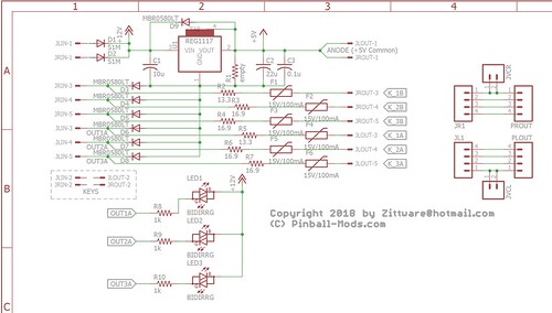
Here’s my original Fab A circuit, keeping in mind this is untested – but I retain all rights to this circuit for the moment:
DE Chase LED conditioner
Some theory of operation:
D1&D2 provide some polarity protection – for paranoia. D3-D8 are the Schottky diodes which provide wired-OR back from the ground of the +5V regulator (U1) back to the chase light board’s OUT* connections.
C1, C2, C3 provide some filtering for the +5Vreg to help it maintain stability with the wired-OR configuration. D9 provides some additional protection for the Vreg – probably not needed; but extra insurance. R2 – R7 provide the series current-limiting resistors for the various LED strings. Why the different values of 13.3 vs 16.9? Well; my quick napkin calculations shows that there may be 5 or 6LEDs on the longest string and then one less on the shorter strings. I plan on connecting the longest string on the 1A & 1B lines while the shorter strings (with the higher resistors) will be on the others. F1-F6 are the resettable PTC fuses. The bidirectional LEDs at the bottom are monitoring the output of the chase light board to give me an indication the chase board is working properly. They will chase green if working properly. I basically created a small “Z-connector” board to condition these LEDs but also added some small connector boards to help me interface from the LED strings to a simple 4 pin 0.1″ pitch latchable connector. The idea is these smaller connector boards would be fixed to the end of the “rope lights” and allow for a quick connection.
A little background on the Series resistor calculations. Basically; Vf isn’t known for the parallel LED strings. You can’t measure Vf with the diode setting of a Digital volt meter which btw; my favorite is a Fluke 87 series meter. Vf according to my DVM is around 2.4V and we know that no current white leds operate at 2.4V for 20mA. Since I don’t know which LED the chinese put in these strips; I had to make an educated guess. To do this I went to digikey.com and drilled down on warm white 603 LEDs, downloaded the table (using the button near the bottom of the page) and then imported the data into excel so I could get an average of the Voltage – Forward (Vf) (Typ) column. I calculated Vf ~= 3.23V. Armed with Vf, and the knowledge I wanted to operate the LEDs near their 20mA operational current so they would be their brightest I was able to calculate a theoretical series resistor. Here are the “knowns”:
Vf = 3.23.
Each LED should operate at ~18mA.
With the ground diode in the Vreg path… assume Vfdiode = 0.4V. This would cause Vout of Vreg to be 5+0.4V, or 5.4V.
“ground” will be thru the UL2003A darlington on the chase driver board. VCEsat = 0.9 min.
Assume 5 leds needed for longest string and solve using Ohms Law. R=V/I.
V = 5.4 – Vfled – VCEsat
I = 18mA * numOfLEDs in string or 18mA * 5
R = (5.4 – 3.23 – 0.9) / (5 * 18mA ) = 14.11 ohms
Subtract off typical Fuse resistance of 0.9ohms and you arrive at ~13.3ohms. Repeat the calculation for a 4 led string and you arrive at ~16.9ohms.
The only “gotcha” with this theoretical calculation is that what happens to the LED if we are drawing near 18mA? There’s no real ground plane or PCB to draw heat away from the LED. The only “heat sink” is the hot glue used to encase the LED and the wire LEDs connecting the LEDs. I’m hoping the low duty cycle of the LEDs will help keep thermal runaway in check. This is something I’ll have to watch in the final assembly. If LEDs start dying… we’ll know it’s either getting too hot… or the parallel LED VF vs current is a problem.
Here’s the Fab A boards as committed to OSHPark. This is their render of the boards as I don’t have them back from fabrication yet:
DE Chase Fab A (Top)DE Chase Fab A (Bottom)
I’ll post more on the circuit boards in Part 2 when I get them back from OSH Park and have them built. We’ll see if my little experiment bears fruit.
Now onto the actual chase lights themselves. I thought about using polyurethane blue tubing from Granger.com as I posted in Pat’s Pinside thread on post #19. But honestly, I don’t really feel like the blue rope light fits the ST:25th theme very well. To me; it looks like some attention getting feature to draw in the eyes of a would be quarter-dropper in an Arcade. Not that is a bad thing; I just figure since I’m not going to an have original rope light assembly with the proper Light spacing… I might as well try to make it fit the theme a little better. If not blue, then what? Well Clear is definitely an option… but it won’t really hide the led wiring very well. I had a lot of extra 1/2″OD, 1/4″ID rigid Acrylic tubing left over from the guide plastics from Star Trek: The Mirror Universe custom pinball project. I was thinking of doing that with some custom Acrylic etches on the tubing. The problem is that Techshop.ws failed due to piss-poor-Management so I can’t really go there to use their rotary attachment on the Tortec. My new-to-me Epilog Laser doesn’t have a rotary Attachment, yet. Not sure what I’m going to do about that yet… Even if I get a Rotary… what would I put on the Tubing? Then there’s the issue of bending it properly… which shouldn’t be too hard given the Youtube videos for Hard Tubing in water cooled case tutorials.
Then I stumbled across ENT Corp on Ebay who seems to have colored versions of this rigid tubing available in cut-to-order. I went ahead and ordered 6 pieces of the smoke acrylic tubing custom cut to 15.25inches. After I experiment with the etching and try my hand at the clear tube bending… I’ll proably finalize the chase lights using the smoke tubing on the final machine.
That’s it for Part 1 of this blog series… I’ll start Part 2 when I get some tubing experiments done and/or when I get the PCBs back from OSHPark. For now, Peace and Long life…
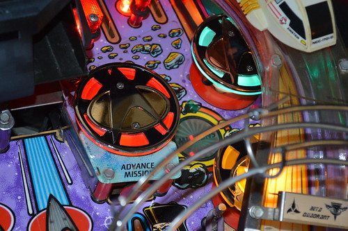
We are pleased to announce the immediate availability of our Star Trek: The Next Generation Popcaps for the 1993 Williams Pinball machine by the same name.
This Popcap kit comes with three high quality Popcaps made of all metal, Zinc Alloy construction and feature a highly polished raised metallic plating for the insignia with a black enamel for the cap’s background. The kit comes with two round caps and one “cut down” cap to fit under the STNG’s beta ramp.
Go from this:
to this:
In addition to the metal popcaps; the kit features a set of laser-cut acrylic Undercaps in your choice of colors. The stock kit offers the Undercaps in uniformed colors – IE one red (Command), one yellow (Engineering), and one light Blue (Science). There are also options to go All Red, or all Purple Undercaps to create a specific look for the game. For lighting; the kit comes stock with a 4-SMD #555 comet LED lamps but offers an upgrade to the 11-SMD popbumper LEDs in either Purple, Red, or uniformed colors. We actually offer two versions of the uniformed color 11-SMD configuration – the first being standard Blue:
with the other intended to match Troi’s uniform color: .
Comprehensive, step-by-step installation instructions are included in PDF form on our product page. This PDF also feature modification instructions for the BriteMods’ BriteCap EVO LEDs as they are the recommended LED product to use with these Popcaps.
Check out KnockerLover’s independant review of our Popcaps on Pinside in his STNG Full Title Modding Thread which is a very impressive read on it’s own. He decided to go with an 11-SMD, all purple configuration which looks stunning when combined his re-imagining.
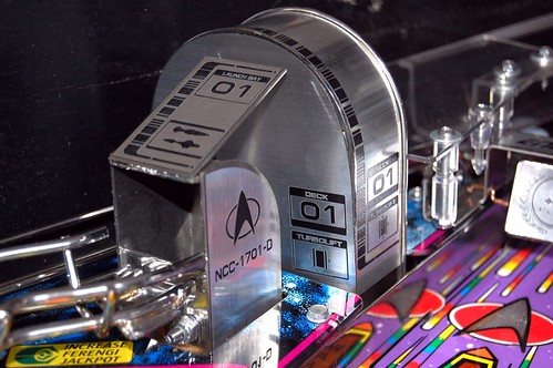
Pinball-Mods.com is pleased to announce we have reached an agreement with Nycon to distribute his laser etched decals for the Star Trek: The Next Generation Pinball machine by Williams in time for the 30th Anniversary and exclusively for the North American Market (USA & Canada). This 18 decal set will provide a much needed face lift for the two VUKs, several brackets, and the three flipper bats in this game. Each decal set is laser etched by Nycon in Germany out of high-quality brushed aluminum decal material to reveal the black plastic underneath.
The decal set dresses up the Left and Right Vertical UpKickers (VUK):
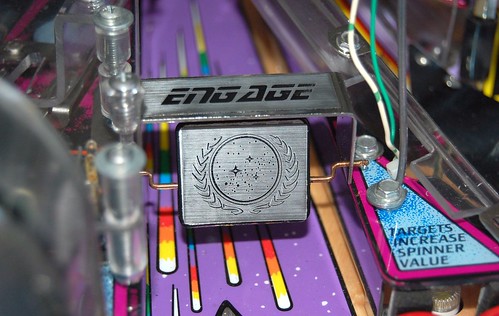
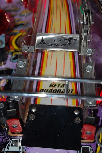
Decals for all three brackets and the spinner:
Flipper-Bat Toppers are also included for all three flippers:
For more information; please see Nycon’s thread on Pinside.
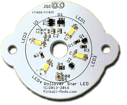
We are pleased to make a delayed announcement of a product which we’ve had in stock for almost a year. This Star Rollover LED board fits on the underside of your Playfield under a Star rollover assembly and will bathe the Star Insert is lower power LED light. With this product you can replace the inefficient horizontal lamp socket and incandescent light bulb with this board:
Each board provides 4 natural white LEDs in a non-polarized light from either a 6.3V source. Because the board has a built-in rectifier bridge; you can supply power from both a 6.3VAC GI circuit or ~6.3VDC controlled insert. You can even control the brightness via a microcontroller PWM signal or from one of the new DIY control systems such as the PROC or its PD-LED driver board.
The design also features a brightness resistor at R5 to allow you to dial the brightness to your desired level. A hole in the center of our PCB allows the actuator to work from the insert to a standard Leaf switch typically under the insert.
A typical installation may require a set of #6-32 x 0.25 inch wood screws so you can bolt it to the back of the playfield under the star rollover insert. Electrical installation is super simple; simply solder the GI connection from the old horizontal lamp socket to the JGI connection, or jump to the nearest GI socket as we did in our machine below. Here is an example installation we did on our Star Trek: The Mirror Universe custom pinball machine.


