I recently purchased a 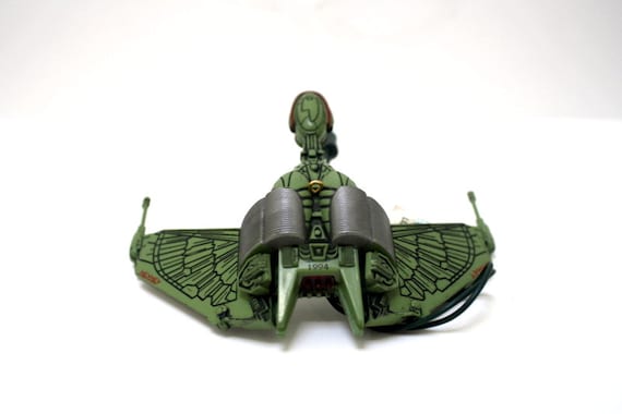
1994 Hallmark Star Trek Klingon Bird of Prey from a fellow Pinsider. This Ornament came ready to install into my 1996 Williams Star Trek: The Next Generation Pinball machine. However before I installed it in the machine; I wanted to make further modifications to the item. My previous installation had installed a die-cast

2005 Corgi Klingon Bird of Prey
for which I’d followed the recommended installation of putting the incandescent light bulbs under the ship:
Immediately upon this installation; I knew it wouldn’t do… but I waited several years until I got one of the hallmark ship mods. I decided back then that I was going to put some Electroluminescent panels under the wings… but then came to my senses that the EL panels loose their brightness rather quickly. So; after getting the Star Trek: Mirror Universe pinball machine to a Phase1 complete state; I returned my attention to this mod. I decided this time that I was going to use superbright surface mount LEDs to replace the light bulbs and their bulky sockets.
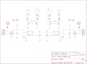
I started by researching the type of LEDs. A Digikey search came up with some super brights; relatively cheap but with a lot of light output. I figured I could fit about three of these LEDs under each wing; so I began the design phase of the project. I started by doing a pencil rub of the wing’s paint job. This gave me an approximate size of the PCB I needed under the wing. I scanned this pencil rub into the computer and vectorized it into a PCB using the technique posted here. With the PCB outline created; I proceeded to create the schematic of the LED board. I made a design choice to rectify the 6.3VAC GI power rail so that polarity wouldn’t matter during install. I also decided that I’d use a BJT current mirror to light the first LED and drive 20mA thru it. Then use the second leg of the current mirror to drive the remaining two LEDs. To ensure stable voltages/currents; I put a 3.3V LDO regulator and some caps on the first leg to try and keep the brightness from flickering with the 120Hz FWB power rail.
I have decided to release the schematics to the public under the TAPR Non-Commercial Open Hardware License which indicates:
You may make products based upon this design, provided you do not make more than ten units in any twelve month period for your personal use.
If you agree with the license terms the resultant schematic is posted here under TAPR/NCL license:
You can buy the bare PCBs from OSHPark from here. Total cost to build this board in single unit quantities as of 6/15/2014 was $14.55 / a pair of boards.
The entire project package is here: STNG_KBOP TAPR Package
It contains the schematic, NCL license, Bill of Materials.
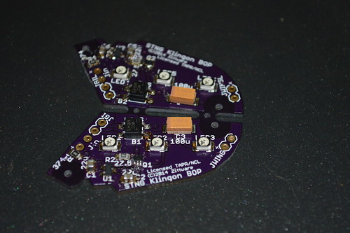
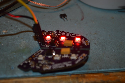
This project requires SMT soldering skills so be prepared. I used a syringe with solder paste to populate the PCBs then used a skillet to reflow the solder. Here’s the assembled PCBs:
Then I assembled tested the circuit first with my 5V bench supply; then with a 6.3VAC transformer from RadioShack:
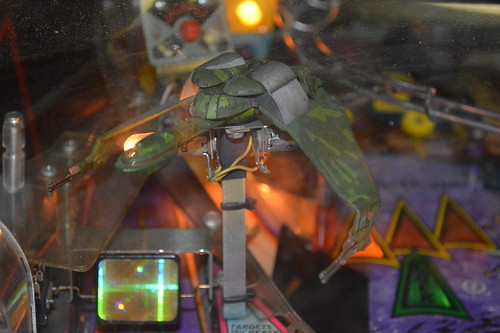
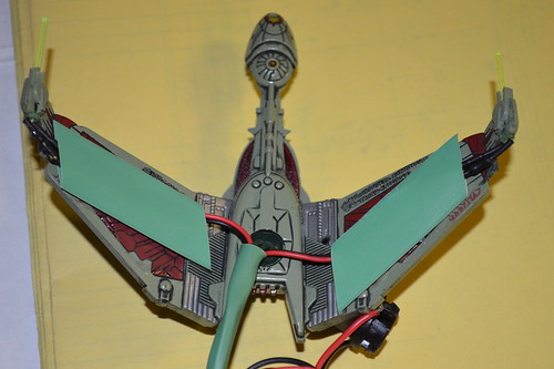
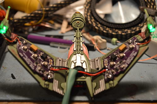
With the boards tested; I began refitting the Hallmark KBOP mod which looked like this:
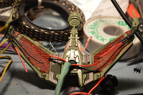
I removed the green heatshrink hiding the LED wing guns and cut the red & black wires as I had recreated the wires in the PCB and had embedded the resistors hidden under the black heatshrink near the guns:
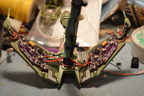
Originally and in the PCB file; I had decided that I wanted to use 2 qty #0 self taping screws to hold the PCBs in place. These were speced at McMaster Carr as #94209a005; but I didn’t want to pay for S&H for that single box of 50. Instead I drilled out the holes a little larger and used #2-56 @ 3/16 of a length. I carefully marked drilled the wings of the KBOP and taped them with my #2-56 tap set. You MUST be careful here not to drill through the wings. Here’s the PCBs mounted:
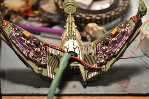
I then proceeded to solder the cut GI wires for the wing guns to the Jin connections on the PCB. I also connected the Guns to the JWing connection at the edge of the PCBs with a short piece of red rework wire after removing the inline resistors at the LEDs. I secured the electrical connections at the gun LEDs with some liquid black electrical tape:
I then proceeded to attach the GI connection from my machine along with the bracket. Reusing the older wireing harness as desoldered from the bulb socket assembly made sure the under wing LEDs lit in the same was as the bulbs:
With that the modification of this mod is complete. Here are some mandatory money shots to encourage you to do the same to your machine:
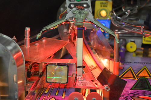

Overall I’m very happy with the results; the Red LEDs really light up the Playfield and I do not have to look at those light bulbs any more. The only thing I noticed with this mod is that my machine doesn’t seem to give me enough voltage at the GI connector to fully lite the two LEDs on the second leg of the current mirror. I think this is because the STNG controls GI; which means there is an extra silcon device between the 6.3VAC transformer and the GI lamps. This is evident when running the shuttle craft missions when all the PF lights are of in this video mode. In a future revision of this mod; I might try directly hooking the second leg of the current mirror straight to the GI input (not FWB rectified) to see if I could coach more voltage across these two LEDs in series.
This PCB obviously fits the 1994 Hallmark ornament seen here and it also seems to fit the Corgi 2005 Klingon Bird of Prey also used in modding these machines.
Enjoy Modding!