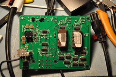
For the last couple of months; I’ve been working on a redesign of the willams printer kit for my Star Trek: The Next Generation pinball. Much of the work as been in the Complex Programmable Logic Device (CPLD) which is in 256BGA form. Why a CPLD? Long term I intend to replace the Intel 8251A USART (which is becoming increasingly difficult to find and expensive) with a “soft IP” core. The only pseudo-free 8251A core I could find was by ALTERA. They allow free use of that IP; but only as long as you put it in an Altera device. I’m ok with that; but to be honest, I really do not like the company. My first tech-support request was “refused” because I wouldn’t provide them with a company or university name. I’m a hobbyist for crying out loud; support your damn products or bite me. If I had any other choice I’d go with another CPLD/FPGA company for this reason alone. But I digress…
This is a 1mm pitch BGA – needed it because the whole design requires logic blocks which only come in bga form factors. 🙁
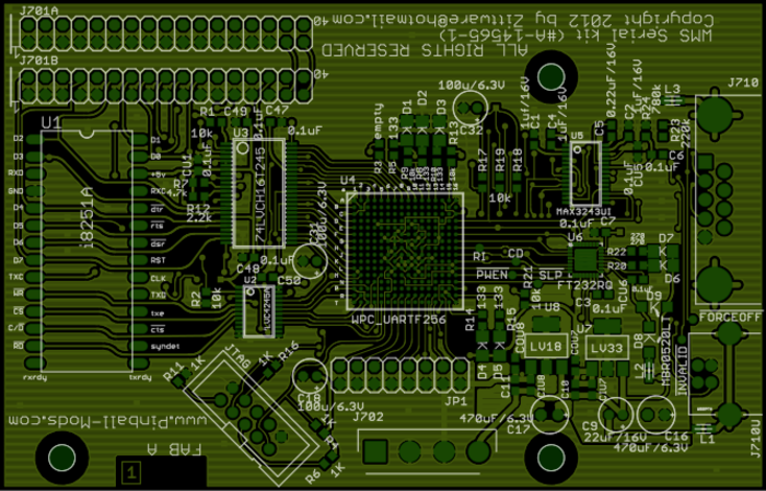
I was forced to go to a 4 layer PCB to get the smaller 13mil drill sizes for “escape routing” the bga signals. I designed the pinout of the BGA to mainly use the outside peripheral pins of the bga. Pinouts were made to make for easier routing to U3 (Ti’s 74LVCH16T245), U2 (Ti’s 74LVC4245A), and U6 (FTDI’s FT232RQ) chips.
The design used the Ti 245s to translate between the MaxV’s VCCIO of 3.3V and the WPC/USARTs system voltage of 5Vs. Linear 1.8V and 3.3V LDOs from Ti drive the MaxV VCCINT (1.8V) and VCCIO (3.3V) pins. 3.3V also drives the other support chips; the UART->USB (FT232RQ) and the RS232 charge pump (U5/MAX3242UI). Logic in the CPLD controls “enables” to the MAX3243 from the USB chip; so that if a laptop/computer is plugged into the usb (J710U); the rs232 port at J710 is “off”.
This leaves a question; Why have the i8251A device onboard. This is a debug feature. Given I’ve never done a CPLD or FPGA design before; I’m thinking it may not work “right out of the shoot”… so I’m providing myself with a short term verification feature; where I can prove a real 8251 works … but there is a bug in the IP core (or my implementation of it). Long term; my goal is to de-pop U1 and U2 to reduce bom costs once the design is proven functional.
The FabA schematics and FPGA high level schematic is posted in the PDF below: Williams Serial Printer Kit (pre-debug)
I retain all rights to the implementation and schematics.
The top layer board will look something like this:
When installing in the pinball machine; one would disconnect the main cpu ribbon cable and plug it into J701B. The connect a short “jumper” ribbon cable from the cpu board to this board via J710A.
I got to be honest; the bga on the board is very scary. $20 a piece… and BGAs aren’t really known for their ease in the DIY workshop. But; it’ll be fun to see how pcb assembly goes.
I hope to order the PCB shortly… then be “waiting” for the batch pcb service to pool with others. I may quote with PCBFabExpress.com as they seem to have very reasonably priced 4 layer boards with a quick (compared to batchpcb, 5 day turn).
Next step after ordering boards and BOM for assembly; is to get back to the visual pinmame source code in order to begin “simulating” the printer kit from a software prospective. Long term; I want to test the ROM hacks to dump the high scores via serial port and the Serial kit. Once I’ve tested the roms in pinmame; then I can commit them to the real machine. I did have some success compiling pinmame from source; but for some reason I get an assertion about filetypes when running the compiled images.
I’d also like a benchtop WMS debug system… thought about using a P-Roc – but not sure if close enough to the original WMS board to be compatible with the WMS printer kit.
Madaracs on the KLOV forums was kind enough to loan me his Sega Captain’s Chair CoinBox for measurement of the dimensions. With his coinbox I was able to modify the preliminary plans I had posted to my Captain’s Chair Restoration.
You may make products based upon this design, provided you do not make more than ten units in any twelve month period for your personal use.
If you agree with the license terms and are interested in the coinbox plans; they are here:
Sega Star Trek Captain's Chair CoinBox Plans (PDF)
Thanks to Muel and Madaracs for the help enabling these plans. Now all I need to do is gain access to Austin’s TechShop to waterjet me some material from these plans.
Almost a year ago I posted in my Star Trek Captains’ Chair worklog that I intended to modernize a old XY Pattern Generator design on the interwebs. Many of the guys on VectorList provided valuable insight into the interworkings of the circuit… and provided many layers of helpful advice.
The result was a working prototype board from BatchPCB.com as a dual sided board. Surface Mount ( yes; I can hear the screams of horror ) as I wanted to minimize PCB size and thereby cost.
There were several key learnings that I’ve noted while building, debugging, and using the Vector Pattern Generator. These learning were as follows and have been incorprated into the FabB design:
The clock generator circuit (3.578MHz xtal) and U1ABC was not “locking”. This was due to the buffered logic of the newer 74HC* logic. Some research on the internet indicated I needed a 150pf cap from pin1 U1A to ground to allow the clock generator to exite enough to lock.
The -12V buck converting power supply wasn’t outputing the correct voltage. It’d start out at ~11V…. the drop to ~5V over several minutes. On my debugged board; shorting R26 (10meg ohm) allows the -12V to become rock steady at -11.8V. Unsure here; the Maxim EE sim was very specific on the 10meg ohm value… but the maxim datasheet indicated two modes for VL to operate in. So for now will error on the practical side.
The 5V regulator did not have enough copper to heatsink to. FAB B has a large 5V copper heatsink built into the board for the linear regulator. For my prototype; I thermal epoxied a small heatsink from a old motherboard onto the top of the regulator to give it some thermal sink.
The Linear POT datasheet was missing details regarding the LED side of the POT. One hole was off and was moved to match the device.
I also included the following “Nice to Haves” into the FabB design:
Retrofitted EPROM sockets to enable A11 for a 27C32 eprom(s)… allowing for more user designed test patterns. NOTE: A11 is hardwired to high to match 2716 eproms configurations. No clock/decode is provided for A11. Future FabC work if a solution can be found.
At this time you can use either 2716 or 2732 eproms in this design.
Renamed topside adj pots to indicate X and Y.
Converted to 3pin jumpers so the jumpers can be mechanically sound when output swing is not shorted.
You may make products based upon this design, provided you do not make more than ten units in any twelve month period for your personal use.
If you agree with the license terms and are interested in the FabB schematics; they are here:
Vector Pattern Generator: Fab B Schematics(Click here to open as PDF)
For those without PCB layout tools; a bare PCB is available from the batchpcb service for under $65. You can purchase the boards from this link: http://batchpcb.com/index.php/Products/91905
The Bill Of Materials (BOM) of the board is available from Digikey for $75.51 (as of this post).
A bom is included with the schematics PDF above, but An XLS file with the digikey part numbers with the complete package of the materials above as a single download: XYpatternFabB_pkg.ZIP You will need to source your own 2716 or 2732 EPROMs as Digikey does not carry them. You’ll also need to source your own 14-16VDC wallwort … you may already have a donor in your parts bin leftover from a defunct piece of equipment.
ROM images for the EPROMs can be downloaded from several sources. Hint: Do a search for XY ROM images .zip in Google.
Use the ROM images as-is for 2716 EPROMs. For 2732 EPROMs; just dup the roms using the following dos commands (as an example):
copy /B X.BIN+X.BIN x32.bin
/B is important as it tells copy that the files are binary, not ASCII files.
The Author is still using the FabA prototype; he has not yet built FabB so YMMV. The changes from FabA were relatively simple; so building these should be a low risk.
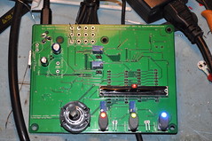
The active components (switches, linear pot, adjustment pots, jumpers, and video connector) are all populated on the reverse side. This will allow me to put the board on standoffs and a acrylic top on the device to protect it from dust/flying multimeter/scope probes.
The board is still quite big even with the surface mount components measuring 5.1×3.9in tall. By far the largest parts on the board are the EPROMs… maybe one day I’ll figure out how to move the EPROMS into a single EEPROM device and surface mount it.
So; what does the Fab A prototype look like?
Click to see higher rez pictures
Vector Pattern Generator: Primary side
This is the primary side; which faces the workbench in normal operation.
Vector Pattern Generator: Secondary side
This is the secondary side. It becomes the “top” of the unit so the user can adjust settings and the like.
Please Note: This implementation is not perfect… there are some issues with the vector generation that I haven’t been able to debug. The imperfection does not really limit the functionality; as you can easily converge and debug a vector monitor with the vectors. I am hopeful someone can help me debug the issues so we can release a better project long term.
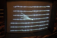
Overall the generator worked quite well as I was able to get my ElectroHome G08 monitor converged.
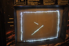
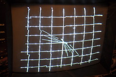
Vector Pattern Generator: Box pattern
I can’t explain the center vectors… nor why the lines become squiggly. They don’t move; it’s always that way.
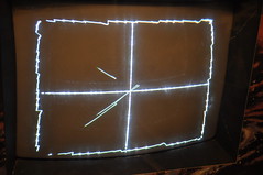
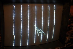
Vector Pattern Generator: Cross pattern
Strange that the site pattern doesn’t seem to suffer from odd vectors.
As you can see; the generator works well enough to converge a vector monitor…
At this point I’m not sure if the odd vectors / none straight vectors are the result of a software problem (EPROM images) or a hardware problem.
It’s possible the software isn’t reacting well with the faster hardware (HC logic, better opamps); but unsure.
Things I still need to do [if I ever find the time]:
check the +12V portion of the buck converter. Right now I’m using the backup +12V linear regulator (U9).
Create an enclosure to house the unit.
Figure out how to clock A11 to enable full 2732 support; thereby more test patterns.
iPhones are rather picky about supporting non-Quicktime video files… as a result my EdiMax IC-7000PTn ip security camera’s motion notification emails weren’t viewable on the device… instead; I’d have to try and remember the external url to the camera and view live. After spending a weekend in Atlantic City for my Mom’s 60th b’day… and getting these useless notifications; I decided to do something about it.
At first; I tried to hack the security camera’s firmware… To complicated with to much risk; as EdiMax doesn’t provide sourcecode for the device… and none seems to have spend a large amount of time on this specific model.
Since I have my IP camera set to dump security motion files onto my LG NAS via FTP, I figured I might as well use the ARM cpu to convert these files using ffmpeg 0.11 and the x264 library to convert the files to a iPhone friendly format. It was a trick to install the x264 library; so please see this post for notes on how I did it. I have root /ssh access to the NAS; unsure if the stock firmware has this so see this post for pointers to the firmware I used. The NAS should have the other prerequisites already installed, but in-case I’ll try to list them all here:
I’ve decided to release the conversion script to the Interwebs via the MIT License for anyone to use. I’d appreciate a talkback/”thank you comment” below if you’ve used it. You can download the script here:
The script is fairly well commented so you should be able to modify it as needed. For the most part; the implementation specific variables are near the top of the script. The Must Change are as follows:
Variable
Description/Usage
sourcelocation
Location of the source videos to convert; typically a “dropbox” ftp-ed in from your camera
backlocation
Backup location of the videos after conversion.
original files are saved for later review
sourceext
file extention for the source videos.
Used to detect new files from “old”.
conversionext
file extention for the converted videos.
Almost always “mp4” as to be compatible with iPhone.
extcamurl
External URL for your IP camera.
Can Specify :port in url for non-80 applications.
Typically a dynamic dns service.
intcamurl
Internal URL for your IP camera.
Can Specify :port in url for non-80 applications.
Used when your inside your home’s network.
Other interesting variables – change may be required
ffmpeg
FileSystem location for the ffmpeg binary.
Use which ffmpeg to find it.
ffopts
holds ffmpeg commandline options for trans-coding to iPhone format.
Could theoreticly be used to trans-code to other smartphone formats.
qtf
FileSystem location for the qt-faststart binary.
Used to reverse Quicktime(iPhone) metadata so video is played immediately instead of downloading.
Use which qt-faststart to find it.
uue
FileSystem location for the uuencode binary.
Used to base64 encode the video files for MIME attachment.
Use which uuencode to find it.
verbose
Set to 0 to keep emails near 1screen on iPhone.
MAILTO
if non-root or non LG NAS; you may need to hard code this to the destination email address to send the notification to
SMTP_AUTH
if non-root or non LG NAS; you may need to hard code this ON for smtp authorization
SMTP_USER
if non-root or non LG NAS; you may need to hard code this a username for smtp authorization
This var is near the end of script
SMTP_PASS
if non-root or non LG NAS; you may need to hard code this a password for smtp authorization
This var is near the end of script
sourceage
number of days the converted files will remain in sourcelocation
backage
number of days the orginal files will remain in backlocation
The script is designed to be run as root via crontab. The Author runs it every minute during daylight hours- this may change when/if he gets additional cameras with night vision. The current version of the script is designed to ensure no other encodings are running – ie more than one instance of iPhone.sh via job control (pgrep). The original video files are backed up to a specific folder and the script makes sure that directory exists.
When sending email using sSMTP; the script will timeout after 90seconds and kill the sSMTP app. You may want to increase this time if you have long videos or a slow Internet connection.
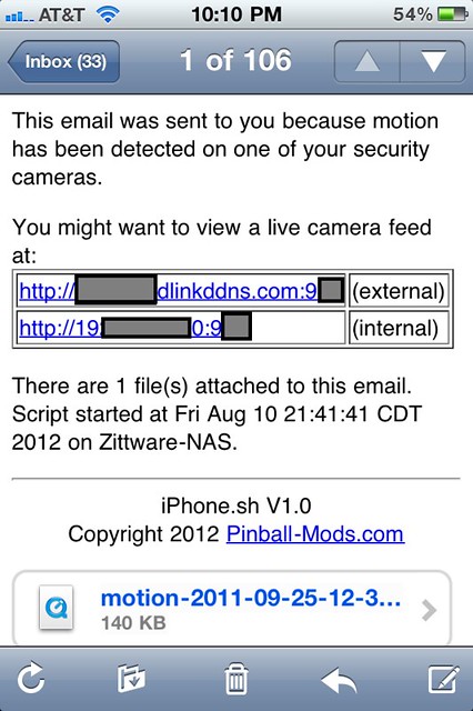
That’s about it… of course, YMMV – but this works very well on my systems and iPhone4. I can get multiple video attachments in a single email; each viewable on my iPhone from the email message.
As an example; here’s a screenshot of the email received on an iPhone4:
V1.1 improvements include a “backup” retiring system thanks to MikeS (a reporter at Hackaday.com) and Hackaday commenter gerphy. Their input included the find commands with some extra sauce to include variables for sourceage and backage.
Feedback is welcome – but all comments are screened by myself to prevent comment “spam”.
Trying to compile the x264 library (x264-snapshot-20120805-2245-stable) for the ARM926 in my LG NAS. Running ./configure seems to give a binary which won’t link with ffmpeg. Config.log in ffmpeg gives the following errors:
/usr/lib/gcc/arm-linux-gnueabi/4.3.2/../../../libx264.so: undefined reference to `d26′
/usr/lib/gcc/arm-linux-gnueabi/4.3.2/../../../libx264.so: undefined reference to `d22′
/usr/lib/gcc/arm-linux-gnueabi/4.3.2/../../../libx264.so: undefined reference to `d2′
/usr/lib/gcc/arm-linux-gnueabi/4.3.2/../../../libx264.so: undefined reference to `d20′
/usr/lib/gcc/arm-linux-gnueabi/4.3.2/../../../libx264.so: undefined reference to `d24′
/usr/lib/gcc/arm-linux-gnueabi/4.3.2/../../../libx264.so: undefined reference to `d0′
/usr/lib/gcc/arm-linux-gnueabi/4.3.2/../../../libx264.so: undefined reference to `q1′
collect2: ld returned 1 exit status
ERROR: libx264 not found
Here’s some random notes I used to make it work:
The .configure for x264 seems to default to cortex9 w/ Neon FPU… not present in my LGNAS. Run configure with the following options:
Where did I get arm926ej-s ? cat /proc/cpuinfo
According to this post; the LGNAS CPU (Marvell “Kirkwood”) does not have VFP support (would be listed as vfp under “Features” in cpuinfo) therefore do not specify a -mfpu= in the CFLAGS.
there is a Star Trek: The Original Series Arcade setup to collect quarters for the Dell Children’s Hospital. Machines On location:
1979 Bally Star Trek
1991 Data East Star Trek
1993 Sega Star Trek video arcade machine
—Update 7/9/2012—
After some personal health issues; tonight I finally got around to doing final count of the quarters. The Summer of 1982 Charity Arcade made $146 in quarters. That amount was submitted tonight (7/9/2012) to the Dell Children’s Medical Center of Central Texas – Area of Greatest Need via their online donation process.
Thanks go out to the RITZ Alamo Drafthouse Team for making the Star Trek Charity Arcade such an awesome success – this wouldn’t have been possible without their support.
I knew this was going to happen; When I first got the wood shell for my Sega Star Trek Captain’s Chair – Someone had already ripped several of the Leg Leveler T-Nuts from the wooden bottom. I figured – hey; can’t be a real problem so I epoxied in some new T-Nuts and went off to Texas Pinball Fest ’12 . Needless to say; three of the T-nuts didn’t make it back to Austin. Call it carelessness; or whatever, but I had to fix this.
T-Nut damage (photo by SaminVA on KLOV)
When I first saw the original t-nut design; I thought it was stupid. The tnuts won’t hold… and neither will those two massive staples the put over the Tnut. If the nut can be pulled; so will the staples. Besides; it’s not like the sell those big staple guns at Harbor Freight or any home improvement store.
I whipped out Corel Draw and laid out some simple plates to “improve” the design. My goal is to make the t-nuts resistant to torque forces while keep the plates simple. Here’s my solution to help keep the T-nuts in place.
The first three items were sourced from Lowes – but nearly any home improvement store should carry these items. The Staples were sourced from Harbor Freight for a previous restoration project. The T-nuts from Mcmaster Carr for the original Sega Star Trek restoration.
The design I came up with is as follows:
I cut the poplar sheet to fit to 24″ length so it would fit on my Laser table. Ran the Laser cutter at 50% power, 1.6 speed, 250 pulses per inch (ppi) to cut on the red lines. The Etches were vector engraved at 40%, 10 speed, 500ppi. Was it necessary to laser cut – heck no, but if you have the equipment; why not use it? Took two passes to cut through the 1/4″ poplar at these power levels.
You can download a full package ZIP file from: Leg Leveler Plate Package
which contains the Corel Draw file and measurements in PDF form.
After Laser cutting; I had these nice plates. Since the wood on the bottom of my Chair was fairly beaten up in a couple of cases; I needed to secure the TNuts with more than just a hammer. I mixed the 5 minute Epoxy per directions at 50/50 ratio and coated the inside of prongs with the epoxy; then hammered in place. I coated the nut with more epoxy in an attempt to secure it better to the wood. Here’s an example of what I did to a friends dedicated Upright Star Trek machine which had simular issues:
Epoxy & wood filler curing on T-Nut
In this picture; some wood filler was used to help secure some missing wood from where the tnuts were ripped out. Be sure not get any epoxy in the threads of the tnut… one way to do this is to run a old leg lever into the hole while the epoxy is setting.
The epoxy sets in 5minutes; but takes a minimum of 1hr to reach some strength; so I let the epoxied Tnut set for an hour and played some Star Trek Pinball.
The plate will be installed with the arrow facing the outside edge of the machine. For the Captain Chair; the orientation of the arrow doesn’t matter as the tnuts are far enough inside the machine to not matter. For the Dedicated upright machines; the Arrow side is 0.1inch shorter; so it will not overhang the front of your machine.
After the hour; I dampened the base of the machine and the plate with some water per directions on the Gorilla Glue packaging. I used the White version; because it cures in about 30-60minutes. I put a spiral pattern on the wood plate and stapled it in place with the 1/4″ crown staples. The Staples provide the clamping pressure while the glue sets.
Plates on Upright Star Trek machine
For the first 5 or so minutes; watch the foaming action. Clean up any over spill of the foam – particularly in the hole near the tnut. After about 5minutes the foaming should stop and you run that same used/scrape leg lever into the threads to keep the hole accessible for your new leg bolt when completed. I used a large blade of the screw driver to scoop out the foam. I put about about 4 staples in an X pattern outside the 1 inch etch hole; which represents the metal Tnut which you don’t want to try to drive a staple into. 😉
I put about 10-15 staples in the plate after initial orientation check – these staples may seem excessive; but I want to secure the wood plate to the bottom of the machine and provide a good even clamping pressure for the gorilla glue to dry. As the package says “Strength of the bond line improves with better clamping.”
Closeup: Plates on Upright Star Trek machine
Wait about 1hr for the gorilla glue to strength… At this point you can gently set the machine back on it’s legs. If you can wait at least 24hrs before any excessive moves – this will allow both the epoxy and the gorilla glue to reach full strength.
Oh; and don’t forget your new leg levers:
Complete!
This plate should be nearly in-destructible; which could prove a problem if the tnut ever needs to be removed. Not sure why that would need to happen – comments / suggestions?
Spent Saturday Evening working the kinks out of my Data East Star Trek 25th pinball machine. When I got it to TPF’12; I started having some issues. These issues needed to be resolved before I take them to the Star Trek: Wrath of Khan showing over the week of June 3rd. While at the Summer of 1982 showing; the machines will collect quarters for a local charity.
Rather than post here; I decided to donate my findings to the PinWiki for other pinheads to use later.
The secondary transformer connector 2F2 was burned; Needed to source a replacement. Created section 3.4.1 Burned Connectors. Complete with burned example pics from my machine.
My Vertical Up Kicker (VUK) switch was worn out and would sometimes not register the ball. New switch sourced from Digikey. Part Number added under Switch Issues
My Sega Star Trek Captain’s Chair is destined to be present at the 2012 Texas Pinball Festival. As a result; the game needs to have a FreePlay feature (IE a way for the public to play the game without needing quarters). I know Sega Star Trek has a freeplay rom hack available; however, at this moment, VectorLabs isn’t supplying freeplay roms with their devices. I haven’t spent enough time with the multi-vector boardset to determine how easy/hard it would be to convert to Freeplay. As a result; I wanted a simple inexpensive way to credit up the machine when the user pressed the Start button (1UP).
I toyed with the idea of using a cheap 8pin ATMEL microcontroller; but decided a simple 555 timer could be developed to do most of the heavy lifting. In the end I decided to go with a dual 555 timer (NE556) in a cascaded mono-stable configuration. The circuit features:
PowerOn Reset to “credit up” a single credit when power is applied to the machine. Jumpered feature.
Ability to drive COIN_NO signals
Ability to “interrupt” COIN_NC
Can be alternatively stuffed for AC power supplies (6.3VAC GI circuits in Pinball Coindoors).
Jumper configuration to “disable” circuit.
Barrier Diodes to help prevent “installation error”.
You may make products based upon this design, provided you do not make more than ten units in any twelve month period for your personal use.
Schematics :
Click to view FreePlay 555 Schematics in PDF
The first timer conditions the active low switch connected to J2-3 (1P [aka the start button]). On the Sega vector hardware; this signal is tied high to 5V via a 2.2K pullup resistor. The start button connects momentary grounds at this signal. The Trigger on the 555 timer is also triggered when the voltage at pin 6 transitions below 1/3VCC. D4 protects the cpu board by preventing current from flowing back into the cpu board. This timer “de-bounces” the switch which sends a single long pulse via OUT1 (pin 5). This timing is created by TA = C6*R4 or ~242mS. I’ll explain the function of R5, JP3, D1, and C7 later.
OUT1 drives the “armed” LED to notify the user/debugger that a “start” pulse was received. OUT1 is coupled to Timer2 via C4 and R6. The purpose of these components is to provide a “negative” trigger pulse at the falling edge of Output. Timer2 then drives based upon TB = R1*C1 or ~60mS. This is the coinup signal which is sent to the coin circuit of the arcade machine. 60mS was derived from measurements of my acutal Star Trek Captain’s Chair by dropping a quarter into the slot via an Oscope.
OUT2 (pin9) drives Q2 and Q1 respectively. When not processing “start/coin up signals” Q1 is “active” providing conduction between the CPU Board and the Switch (PNP active when base is low). On the sega star trek; I found that I had to interrupt the NC signal of the switch in the coin door to get the cpu to “detect” a coin from our COIN_NO (J2-4) – Q1 provides this interruption. Speaking of NO, Q2 goes active when OUT2 outputs a high… which drives a “low” to the COIN_NO. In the Vector machine; COIN_NO is pulled high thru another 2.2k resistor and drives the !Set signal of a Set/Reset Latch made out of NAND gates. Incidentally; the NC signal drives the !Reset signal. The Q output of the NAND gate drives the clock of a D latch which drives the interrupt pin to the cpu board.
I promised to talk about the R5/C7 combo. These components control the “poweron” coin up timing. TpwrCoin is a function of U2’s timing and R5*C7 which is basically ~1.2seconds. U2 is a ActiveLow microprocessor supervisor IC. It monitors the 5V powersupply and holds !RST low for about 150mS. This allows the top of R5 high thru a 5.5k internal pullup resistor when the device is non-active. Meaning U2 will drive RST high on each timer after 150ms once the 5V rail is at least within 15% of the 5V target (4.25V). This effectively provides a “credit” signal to the game about 1.2seconds after the power button is pressed (for initial credits). In theory; this circuit can be disabled by removing JP3’s shunt.
JP1 provides a mechanism to “disable” the freeplay circuit. IE virtually removing the circuit from your game. Use this in position [2-3] to disconnect the timers from the bases of the transistors which should return the game to normal operation. IE if you want to start charging people money. I plan to use it to enable money when I take it for charity work.
Please be aware; this circuit still allows the coin shutes to work… even if the circuit is enabled. This was intentional.
The PCB is designed as a two layer PCB with through-hole parts on the top layer to enable those less skilled with a soldering iron to build the circuit.
FreePlay 555 Fab A Top Layer w/ Silkscreen
FreePlay 555 Fab A Bottom w/ Silkscreen
For those without PCB layout tools; a bare PCB is available from the batchpcb service for under $14. You can purchase the boards from this link: http://batchpcb.com/index.php/Products/75967
The Bill Of Materials (BOM) of the board is available from Digikey for $9.02 (as of the time of this post). A bom is included with the schematics PDF above, but An XLS file with the digikey part numbers with the complete package of the materials above as a single download: FreePlay555_pkg
The author’s prototype was built from mostly RadioShack parts he had in his parts bin including the breadboard. He intends to replace this with a PCB from batchpcb in a few months.
Installation note: You need to make sure this circuit used the same voltage rail of your cpu board. The authors’ G08 wiring harnesses did not follow either the Cockpit (which is correct) schematics or the Upright harness (which is incorrect). The J4/P5/p12 harness shows that the cockpit connects the coindoor lamps to the +5V rail at P5 pin6 and pin8. However, The author’s harness had it connected to the -5V rail which is BAD and will prevent the circuit from working properly (and possibly damaging your machine). The upright schematic shows that +5 and -5V goes to the lamps for 10V… also bad.
Either wire up a new +5V signal to this board; or correct your wiring harness to be like the schematics of the cockpit. Seriously – go double check it.
I wired in this circuit into the coin door harness so the board can be bolted to the inside the door. You’ll need to “cut” the NC wire of one of your coin switchs and put this circuit between it at J2-5 and J2-6. Then wire in the NO signal at J2-4. The Start Button goes to J2-3, the +5V rail to J2-1, and Ground to J2-2.
The circuit works as expected in my machine…. providing an inital “Free” credit upon powerup and then providing additional credits each time the start button is pressed (after the game starts). If you want more than one credit; the circuit can be redesigned; or you can press start multiple times during your “inital” game. 😉
I’m fairly sure this circuit can be adapted to any arcade machine. I provided a bridge rectifier stuffing option at B1 to enable “AC” voltage inputs from 6.3V AC. Or Jp2 can be “bridged” with solder to enable 5V to via the D3 shottkey diode. I plan to test this circuit on my Bally Star Trek Pin once I get the PCBs back.
Enjoy… I’ll post more pictures when I get the PCBs back from batchpcb.
For those following my Sega Star Trek Captain’s Chair restoration; I replaced all the bronze plexiglass with some newer Transparent Grey Acrylic which did not have scratches. One of these peices was featured in the Restoration Worklogs at AustinModders.com or KLOV.com where I custom laser etched schematics of the Klingon D7 crusier and the Nomad Probe:
At the time; I predicted that the etch would not show up well once it was installed in the chair:
Sadly; that prediction came true. As a result; I decided I wanted to find a way to lite the etch with LEDs. SeaWolf on KLOV mentioned to me that he planned on lighting his Chair with some red lights to give it a “battle stations” feel while playing… I told him at the time; I’d proably steal his idea … which is the update your reading about now.
To light the Etch; I decided to create a Red Light bar under the custom Black Corner piece I created when I destroyed mine. But before we go there; I had to decide HOW to create the light. I decided I wanted mine to “activate” when a new game was started and then automatically turn off when the game was finished. I don’t have access to the Star Trek source code; so a software hack seemed problematic. Hummm… What’s the next best thing? Audio! With the exception of attract speech from Scotty and Spock; the instructional videos are silent. So I decided I wanted my machine to go into “Red Alert” Mode when real game play audio starts.
The Red Alert Audio circuit was born. 😉 I spent several nights running spice simulations and came up with this circuit which I’m donating to the public under the TAPR Non-Commercial Open Hardware License which indicates:
You may make products based upon this design, provided you do not make more than ten units in any twelve month period for your personal use.
Schematics :
Click to view Red Alert Audio Schematics in PDF
The only IC in the circuit is U1, a dual JFET opamp – TL062P which operates from a single supply at ~12VDC. U1A makes up a 13.5x amplifier to amplify the ~100mV speaker signal from J1-1. The amplifier operates in non-inverting mode; so the gain is derived from 1+R9/R7. R6 is a series resistor intending to limit the loading of the audio amplifier (prevent distorition) and impedance match closer to the that of the 8 ohm speakers present in the upright version of the Sega Star Trek. D1 and D2 provide over/under voltage protection for U1A; limiting pin3 to 12+0.7V and ground (-0.7V) – a real possiblity given the audio amp is powered from a split supply @+/-24V. C2 is a DC blocking cap to prevent our single supply opamps’ bias voltage from loading the sega’s audio amps. R10 provides a high resistance path to our bias voltage of ~6VDC.
The second opamp (U1B) operates in comparator mode; comparing to the voltage divider made up of R4 and R5. V+U1B is (R5*Vcc/2)/(R5 + R4) or 100k*6V/(110k) or 5.46V. If we have no input audio; Pin1 floats above our bias of 6V; forcing the comparator to drive low providing no voltage to the remaining circuitry… effectively an off. Once the amplified input exceeds (6V-5.46V) 546mV; charging current is sent to D3. For those paying attention; 546mV /13.5V/V… means the input voltage at J1-1 must exceed 40mV regularly to charge the capacitor at C1. Empircal evidence on my Chair indicates that “Thrust” alone generates ~100mV at Pin3 of the U1A. Ofcourse your mileage may vary depending on a number of factors including your current volume level.
Once Pin7 of U1B begins to provide a voltage it is channeled to the RC circuit made up of R2&C1. Since the comparator swings between ground and ~+12VDC; it take nearly zero time for the capacitor C1 to charge to full capacity ~R3*C2 or 3.5mS. D3 provides blocking to prevent U1B from loading the RC circuit and R3 provides load resistance to prevent “shorting” the opamp to ground while C1 charges. Once U1B turns off; the RC circuit becomes a voltage source for M3. R2 slowly drains C1 meaning Toff = R2*C1 or ~8.6seconds. This time delay is necessary to ensure the red alert bar doesn’t go off in the middle of a game… IE between Sectors.
R1, Q2, and Q2 make up a BJT Current Mirror with M3 becomming the “on/off” switch for said mirror. When the gate exceeds approx 3.3VDC; M3 turns on conducting R1 to the top of Q1. Since we tied V+ (J2-1) to the 12VDC PSU in the sega G08 Card Cage; We can calculate the reference current into Q1. Iref is (V+ – Q1_VEB)/(R1 + M3_Rds); assume Q1_VEB=0.7V and M3_Rds from datasheet is 5ohm max. Iref is (12-0.7)/(681+5) or 16.5mA. Given Q1=Q2; ILED @ Q2 (J2-2) is 16.5mA; meaning we now have the means to pull 16mA thru up to 5 LEDs. Given my planned use is ~2V super bright Red LEDs; we can fit at most 5 LEDs in the leg of the current mirror before we run out of voltage. Q4 is a secondary Current Mirror “channel” to allow me to drive another 5LEDs… so I now have a means to drive 10 LEDs in the Red Alert Lightbar.
The powersupply for the circuit is made up of D4, C4, and C5. D4 provides a blocking diode incase I screwed up the wiring. C4/C5 provide filtering given the 12VDC source is about 12feet away. D5, R11, and Q3 make up a simple linear regulator to derive the 6VDC (VCC/2) biasing voltage to U1.
Whew! – clear as Mudd? There was some detail there; hope some of it made sense. 🙂
The PCB is designed as a two layer PCB with through-hole parts on the top layer to enable those less skilled with a soldering iron to build the circuit.
Red Alert Audio Fab B Top Layer w/ Silkscreen
Red Alert Audio Bottom w/ Silkscreen
For those without PCB layout tools; a bare PCB is available from the batchpcb service for under $15. You can purchase the boards from this link: http://batchpcb.com/index.php/Products/70379
The Bill Of Materials (BOM) of the board is available from Digikey for under $6 (as of the time of this post). A CSV file with the digikey part numbers is here: RedAlertAudio_FabB_bom.csv
Here’s a package of the materials above as a single download: RedAlertAudio.zip
Here is the the prototype assembled:
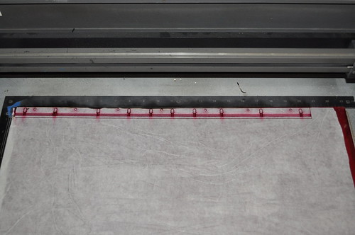
Now I needed to find a way to mount the 10LEDs under the black corner piece. This was done by laying out a 1inch strip of Red Acrylic in Corel Draw and laser cutting said peice:
I decided the LEDs would be wired as a “circuit” on the Red Acrylic. My LEDs are 5mm in size; so these would edge light the 1/4inch red acrylic. I put in 40mil traces in the design which are etched on the laser cutter to give us groves to put the LED leads in:
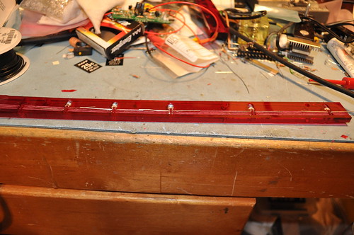
5 of the LEDs were placed on the right side with the Cathode of LED1 at the far left side end. LED2’s cathode is wired to LED1’s Anode repeating until the LED 5’s Anode which is then wired back to the left hand side. When the LEDs touch; they are soldered in place. When they don’t touch a piece of Adhesive red rework wire is soldered between the leads:
The Anode is wired back to the left side by the red rework wire. The Anode of the second 5 LEDs is then tied to the Anode of the first 5LEDs and the cycle repeats in reverse until the cathode of LED1 is at the right most side. It is then tied with a peice of Black adhesive rework wire back to the left hand side. This provides a “single” connection side for all the LEDs.
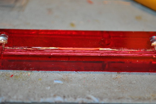
Here’s the finished Circuit on Acrylic:
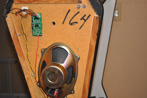
I twisted about 12feet of yellow and black wire together and wired it into the connector on the G08 PSU at the +12VDC lines; it terminates on pin 1 of J1. The LED connections also terminate on J1. I drilled a couple of 7/16″ holes on the right side of the chair near the speaker using the circuit board as a template; making sure not to go all the way thru the side wood – just deep enough for the hex standoff threads. I then tapped these holes with a #6-32 tap; and placed a set of #6-32 hex standoffs in the holes. A couple of #6-32 screws and the board is now mounted at the top of the chair:
I found that I didn’t need to wire the speaker ground from the PCB to the speaker; instead only wired from the + side of J1-1 to the + side of the speaker. A small 7/16″ hole was drilled thru the wood to allow the 3 rework wires to come thru to the PCB. Given rework wire is fragile, small, and solid core; I put about 3″ of stranded 26 gauge wire before the crimp style connector. All of the excess wire was tye-wrap anchored to side of the wood -leaving plenty of “service loops” to enable future changes.
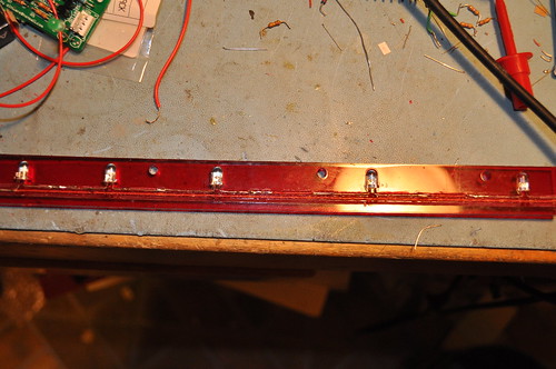
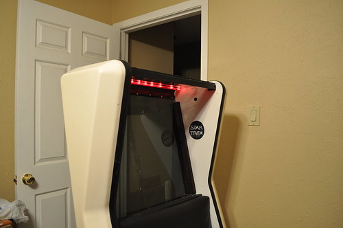
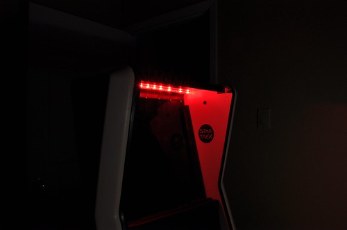
So… was it a success?
Does it Activate as expected?
While the circuit works as expected; it fails to deliver the intended effect of lighting the Window etch properly. Still a cool effect; one I’ll keep… but I’ll need to give the etch lighting some more thought. I’m also going to try and increase the current thru the LEDs by adjusting the R1 reference resistor. The LEDs should be able to handle close to 20mA (package says 24mA max); so the increase in current should brighten them up a bit.


")